Abstract
Cooling fan, as an important component of the Off-Highway machinery cooling system, is becoming the largest noise source when it is rotating fast. So, it is the key to suppress the noise from cooling fan in reducing noise in the Off-Highway machinery. In this study, we designed a kind of non-smooth surface cooling fan which could reduce noise strongly, by adding two kinds of non- smooth features on the smooth surface of the forward-skewed fan, and also combining the CFD virtual wind tunnel simulation with bench test to analyze features of flow field and noise. Comparing the experimental data shows that the new fan effectively suppressed the vortex of the power cabin; the effect to reduce noise is proportional to the rotate speed, and with the rated speed, the total noise is reduced 20.9 % and the peak noise is reduced 21.5 % than the original arc bending plate fan in wheel loaders.
1. Introduction
Cooling fan, the key component of the Off-Highway machinery, is responsible for decreasing temperature of the radiator module and keeping the thermal steady of power cabins to make the whole machine operate safely and reposefully. While Off-Highway machinery is operating in heavy load, the cooling fan is rotating fast. Blades cutting air will produce continuous pressures that result in lots of noises. As we all know, noise not only is a public hazard, but also has influences on drivers’ health [1].
Currently, researches about cooling fan are mainly focusing on the middle or small diameters of fans, such as electronic produces, while less on the large diameters of cooling fans in the engineering vehicles or other kinds of Off-Highway machinery. Yaroslav [2] reduced the high-frequency noise by using leaned stator blades in the Aircraft fan, which decreases tonal noise by approximately 5.0 dB and broadband noise by 2.0 dB in comparison with radial stator vanes. Zeng [3] thought the experimental study of 6 groups of forward-skewed and backward-skewed fans found that increasing the intensity of the inflow turbulence intensity affects both tonal and broadband noises. The impact is greater for the forward-skewed fans than for the backward-skewed fans. Canepa [4] experiments on the axial fans found that SPL noise is mainly affected by the tip leakage flow. Researches on the comparisons of different speed spectrums showed that tip leakage flows were affected by rotational speed and operating point of fan. It can be seen that both the Zeng and Canepa studies are confined to small-diameter low-speed fans, and their analysis focuses on the theoretical analysis of noise generation mechanisms but lacks practical engineering verification. Yaroslav’s research, although effectively in reducing high-speed fan noise, but high technical requirements hinder its promotion. This study is improving fan design to the cooling fan of some wheel loader to optimize the reduction of noises. By analyzing the mechanisms of producing aerodynamic noises from cooling fan and based on the high frequents and low frequents noises, we used two different non-smooth features to make the restriction, and also redesigned a strengthening noise reduction cooling fan according to the non-smooth face fan leaf of this wheel loader cooling system. We analyzed the influence of the new fans on power cabin by the combination of CFD stimulation with the tunnel wind test, and also compared the new fans with the aerodynamic performance and noises level of arc bending plate fans.
2. Turbulent noises model
Lighthill had studied deeply on noises produced from flow [5]. There are three reasons for the production of turbulent noises. The first one is the turbulent boundary layer of the airfoil face which causes pulsation of surface pressure. The second is the excessive turbulent speed existed in incoming flow. The other one is the drop of trailing edge vortex of fans’ trail. Noises from Trailing-edge and tip vortex are broadband noises whose frequency range are 750-2000 Hz. They are the main high frequency noises. Mostly, noises from fan-apex flow are small to Mid-frequency which is less than 500 Hz. The Off-Highway machinery has features of slow speed, large load, flat condition, and the flow fields in its power cabins are more stable than in commercial or passenger vehicles. Because of the relatively slow flow speed of the interior air, the noises from Off-Highway machinery are trailing-edge and tip vortex formation noises. This study is using the formula of semi-empirical wind power airfoil noise which is proposed by Brooks Pope [6] and Marcolini from the national renewable energy laboratory. This formula is that Brooks Pope and Marcolini semi empirical formula optimized to the CLARK-Y airfoil.
2.1. Turbulent boundary layer trailing-edge noises
When the turbulent boundary layer which is attached on the fan leaf passes through the trailing-edge and reacts with the edge, the turbulent boundary layer trailing-edge will be produced. In some angle of attack and Reynolds number, the surface laminar flow of airfoil will be changed to turbulent flow. Then at the posterior trailing-edge, the flow fields produce pressure fluctuation. The shape and thickness of trailing-edge have more influences on these noises. Recently, the main method to reduce trailing-edge noises are modifying the shape of airfoil and applying blade trailing edge [7]. Noises of trailing-edge of turbulent boundary layer Eq. (1) () are the combination of the sound pressure level Eq. (2) () and suction pressure level Eq. (3) () of turbulent boundary layer:
2.2. Tip vortex formation noise
The tip vortex formation noise is calculated according to Eqs. (4-5). Based on the theory of Three-Dimensional Flow [8], at the fan apex, the rapid spinning leaf will form vortex which produces low-frequency noises by the collision and friction with the wind scooper. The general adapted method is improving the design of fan-apex, using the stair-stepping fan apex or jagged trailing edge that could damage the formation of vortex and reduce the effect of fan apex vortex [9]:
where , is the attack angle of fan apex, is the speed of fan apex.
2.3. Airfoil optimized mathematical model
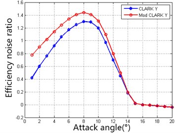
The analysis of the first two chapters shows that the airfoil noise is closely related to the boundary thickness of the top and bottom surface of the airfoil. Designers are pursuing larger lift-drag ratio () of the airfoil in order to get a better aerodynamic performance, but the increase of life-drag ratio causes the decrease of structural strength and the growth of noises. Therefore, the efficiency noises ratio which is the objective of Eq. (6) is the ratio of to . The mathematical model was established to process the optimized solution [10]:
We were applying the MATLAB genetic algorithm to objective Eq. (6) to get the optimized solutions [11, 12]. The optimize result of CLARK-Y airfoil shown as Fig. 1 the optimized MOD CLARK-Y airfoil has higher efficiency noises ratio in the whole attack angle.
Fig. 1Comparison of efficiency noise ratio
3. Design of the non-smooth surface fan
The factory standard of some certain wheel ladder is arc bending plate fan which has large flow and simple structure, while it did not take noises into consideration, which leads to the heavy noises pollution when it overloads work. According to the request of the power cabin radiator of the wheel loader to the pressure loss and mass flow rate (Table 1), we took advantage of the forward blending fan as the basis and combined with the advance of reducing noises of the non-smooth surface fan to design the non-smooth surface cooling fan which could reduce noise strongly.
Table 1Design requirements of cooling fan for the wheel loader
Diameter | Rated speed | Mass flow rate | Static pressure | Fan leaf number | Hub ratio |
780 mm | 2000 RPM | 9.4 m3/s | 375 Pa | 7 | 0.32 |
3.1. Selection of forward-skewed angle
The forward-skewed fans are designed based on the method that the gravity line of the section blending forward. This is one of the effective methods to reduce noises, but the disadvantage is the larger angle of the forward blending will cause the speed distribution varies on the surface and also leads to intensify the vertex that results in the decreasing effect of static pressure. In this paper, according to the method of literature [13], the CFD simulation shows that the efficiency of the static pressure in cooling fans is the highest when the forward-skewed angle is 6 degrees. Thus, we used the gravity line at blending forward 6° and MOD CLARK-Y airfoil to establish the physical model of cooling fans.
3.2. Non-smooth fan leaf
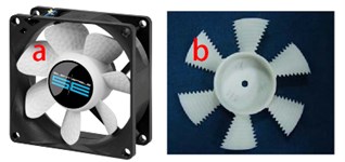
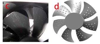
The general non-smooth surface designs of the small diameter fan leaf are bump type (Fig. 2(a)), trailing edge serrated type (Fig. 2(b)), type of drag reduction of flexible surface (Fig. 2(c)), and perforation type leafs (Fig. 2(d)), which are adding non-smooth characteristics on the whole surface.
Fig. 2Surface characteristics of common blade
However, the fans whose diameters exceed 500 mm cannot ignore their own weight, particularly most of the present Off-Highway machinery with metal materials. We should not only consider the lift drag, but also the stress state of the fan when it is rapidly spinning. Through CFD virtual wind tunnel simulation, we found that if we design by applying the leaf perforation of small diameter or bump type surface to the larger diameter, it will lead to the deficient of the fan mechanical strength. Stress will be concentrated easily on the surface, which causes the deformation or break of the fan when it is in heavy load. So, if using the non-smooth design of the whole fans as we present previously, we need to thicken or redesign leafs in order to confirm the mechanical strength. This will increase the driving power drastically, and also will raise manufacturing costs.
This study put forward that adopting part of the non-smooth surface design on the large diameter leafs of Off-Highway machinery changed the geometrical parameters as less as possible and took advantage of the simple and easy manufactural features. Combining characteristics of wheel loader power cabin, we improved leafs as follow: using stair-stepping fan apex in the fan apex; adding five gradually shallowed jagged apertures in trailing edge; incorporating three heaves with stripes. Then the non-smooth surface fans are produced by the combination of these features.
4. Analysis of the flow field on the non-smooth surface
4.1. The physical model of the non-smooth surface fan
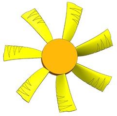
We used UG to establish the physical model of forward-skewed fan (Fig. 3). According to chapter 1.2, we adopted the original smooth blade apex to stair-stepping blade apex and used jagged trailing edge, in order to decrease the effect of vertex to make the vertex noises restrained. High frequency noises are from turbulent loss of the blade surface. Three heaves with stripes thicken the blade center and trailing edge. This makes the laminar flow dropped difficultly to transform to turbulence or delays the location where fluctuating pressure produces, which reduces the pressure that formed by the drop of pressure and suction surface and decreases noises from trailing edge; in addition, this feature could also take some increases of static pressure and effects of drainage. The non-smooth surface fan (Fig. 4) is the combination of the non-smooth surface blade (shown in chapter 3.2) with the forward-skewed blade.
Fig. 3Model of forward-skewed fan
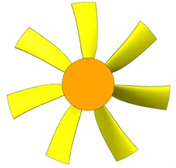
Fig. 4Model of the non-smooth surface fan
4.2. Simulation analysis of cooling fan flow field
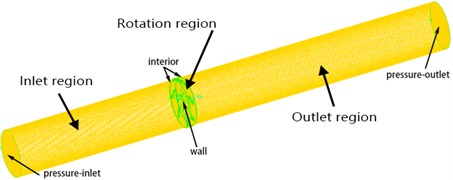
In the field of Off-Highway machinery, any cooling fan should be satisfied with the flow of the power cabin and the depressurization request of the radiator module. Establishing flow field analysis virtual wind tunnel by using UG, we analyzed the flow fields of arc bending plate, forward-skewed and non-smooth surface fans, respectively, by Fluent [14]. The diameter of the virtual wind tunnel is 780 mm; the length of the inlet region is 3120 mm, and the length of the outlet region is 4680 mm. Mesh the wind tunnel model with Gambit as shown in Fig. 5, the total grid number is 2625785 and the grid quality is 0.75, which meet the simulation requirements, and the mesh parameters of each part are shown in Table 2. The boundary conditions of Fluent are set as follows: The fan surface set to wall; the wind tunnel inlet sets to pressure-inlet; the outlet of the wind tunnel sets to pressure-outlet; the inlet and outlet of the rotating region set to interior.
Fig. 5Fan calculation area grid
The environmental parameters and material physical parameters used in the simulation are as follows: the pressure sets to standard atmospheric pressure which is 101325 Pa; ambient temperature is 35 °C; the fluid medium as air whose density is 1.225 kg/m3; the dynamic viscosity is 1.7894e-5 kg/m·s.
Table 2Grid parameter of virtual wind tunnel
Type | Quantity | Interval size | |
Rotation region | Hex | 937185 | 1 |
Inlet region | Ted/Hybrid | 560800 | 10 |
Outlet region | Ted/Hybrid | 1127800 | 10 |
Total | 2625785 |
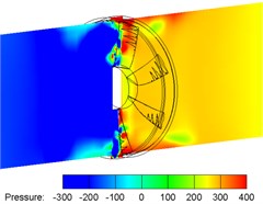
The comparison of the contours (Figs. 6-8) of static pressure of in and out section shows that the low pressure areas of air intake of the arc bending plate fans is smaller than the forward-skewed fan, and also the areas are distributed on the top of blade unequally, but the low pressure areas of forward-skewed fans are distributed between roots to top of blade; in outlet side, high pressure areas of the arc bending plate fans are only located near the top of blade, while the forward-skewed fan are all high pressure areas in the middle-upper parts of blade; the aerodynamic performance of non- smooth surface fan is better than the other two fans, but there is some pressure drop in the air outlet side. Although the non-smooth surface fan reduces the vortex at trailing edge, the losses of some fan areas cause small decrease of pressure and flow.
Fig. 6Pressure contours of arc bending plate fan
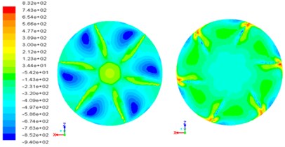
Fig. 7Pressure contours of forward-skewed fan
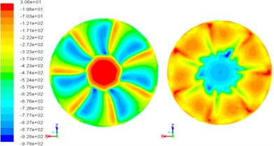
Fig. 8Pressure contours of the non-smooth surface fan
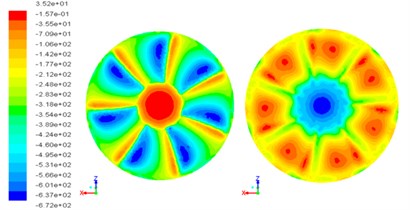
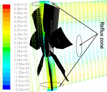
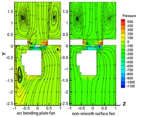
According to the result of the wind tunnel simulation, we find that the low pressure area is larger on the outlet side and the reflux zone on the inlet side is larger than the other two fans (Figs. 9-10). The low-pressure area of the forward-skewed fan is concentrated near the hub and smaller than the arc bending plate fan but its static pressure is lower than the arc-bending fan (Fig. 11). The low-pressure area and the inlet side vortex of the non-smooth surface fan are the smallest in these three fans and its flow field uniformity is the best (Fig. 12).
Fig. 9Velocity contours of arc bending plate fan
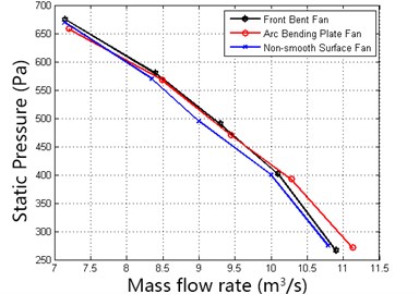
Fitting the mass flow rate and static pressure of the three fans in rated working condition (Fig. 13), we find that the forward-skewed fan is almost similar with arc bending plate fan in pressure and mass flow rate, and only slightly lower in the max mass flow rate; because of the introduction of non-smooth surface design and stair-stepping blade apex into the non-smooth surface fan, there is some losses of blade areas, which leads to the relatively weaken. However, the improvement of the design strengthens the homogeneity of flow field, so the effect of air intake and outlet is better than other two fans.
Fig. 10Pressure contours of arc bending plate fan
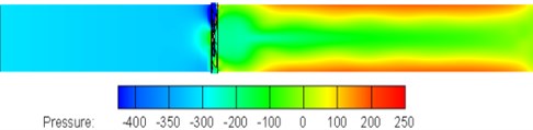
Fig. 11Pressure contours of forward-skewed fan
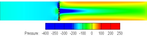
Fig. 12Pressure contours of the non-smooth surface fan
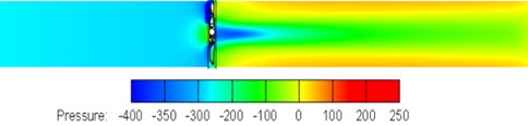
Fig. 13Rated speed fan performance curves
The results from the CFD simulation of the non-smooth surface fan in certain rotation speed are that the mass flow rate is 10 m3/s and the static pressure is 407 Pa, which are satisfied with the design requests of the certain type of wheel loader cooling fan in Table 1.
Fig. 14Model of the power cabin
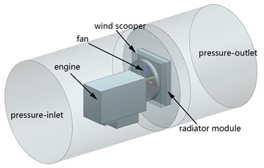
Fig. 15Pressure contours and streamline of power cabin
In order to study influences of different fans on the flow field in the power cabin, the model of the power pack of the wheel loader is established as shown in Fig. 14. The left of Fig. 15 shows the velocity-flux contour map in static pressure of arc bending plate fan power cabins. The static pressure is a little higher, but the interior of the cabin and air intake side of the fan have obvious vortex; while there is no obvious vortex in the interior of the power cabins of the non-smooth surface fan (Right of Fig. 15). The arc bending plate fan is higher than non-smooth surface fan in the part of radiator reflux; Comparing with the outlet flow field, we find that the reflux zone in up and down of the non-smooth surface fan approaches to the two sides of boundary, and the area of the central stable flow field is small bigger than the arc bending plate fan. These are also conformed to the analysis of the two kinds of fans.
5. Aerodynamic noise analysis of non-smooth surface fan
5.1. Simulation of aerodynamic noises
In a certain velocity, we combine aero acoustics LES and FW-H Model to simulate [15]. LES is to get the solution of transient turbulent flow firstly and then do not start the noises model calculation until the pressure is stable. The FW-H [16] control formula shows like Eq. (7):
Firstly, the pressure field of three kinds of fans is solved by LES model. After the pressure field stabilized, the acoustics model is used for noise analysis [17, 18]. The central section of each fan when the pressure field is stable is shown in Figs. 16-18. Frequency spectra of the arc bending plate fan shows in Fig. 19. The noise frequency is mainly distributed within 2000 Hz, and the highest sound pressure level is between 100 dB-130 dB. The main noise frequencies of the forward-skewed fan and the non-smooth surface fan are also distributed within 2000 Hz, but the highest sound pressure level of the non-smooth surface fan is lower than that of the arc bending plate fan as shown in Figs. 20-21.
Fig. 16Pressure contours of the arc bending plate fan (LES Model)
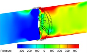
Fig. 17Pressure contours of the forward-skewed fan (LES Model)
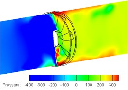
Fig. 18Pressure contours of the non-smooth surface fan (LES Model)
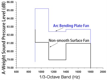
Arc bending plate fans do not use any reduced noises design, so they are higher than forward curved and non-smooth surface fans no matter in high or low frequency noises. Compared to the arc bending plate fan, the non-smooth surface fan has obviously reduced noises in the low frequency noises 0-750 Hz (Fig. 22), which explains that the stair-stepping fan apex and jagged trailing edge fans decrease the tip vortex and restrict the production of noises; in the high frequency noises 750-2000 Hz, non-smooth surface fan is lower than arc bending plate fan as well (Fig. 23). This illustrates that the heave with stripes slows down the drop of laminar flow in the fan surface, and inhabits the fluctuation of the pressure from the drop of the turbulence on the up and down surface.
Fig. 19Frequency spectra of the arc bending plate fan
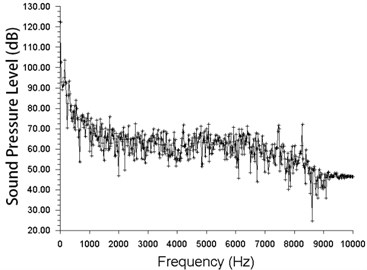
Fig. 20Frequency spectra of the forward-skewed fan
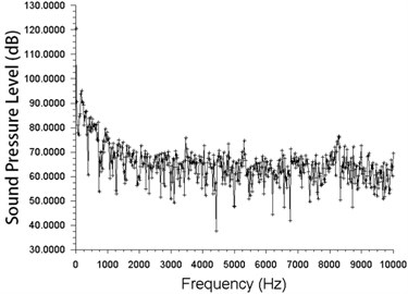
Fig. 21Frequency spectra of the non-smooth surface fan
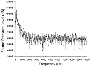
Fig. 22Comparison of low frequency spectra (frequency range of 0-750 Hz)
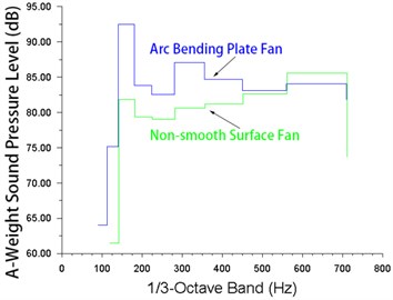
Fig. 23Comparison of high frequency spectra (frequency range of 750-2000 Hz)
The Fluent simulation result of A-Weight sound pressure level and peak noises is that: The A-Weight sound pressure level superimposing noises of the original arc bending plate fan of the wheel loader is 115.8 dB, the forward-skewed fan is 107.6 dB and the non-smooth surface fan is 95.5 dB; in peak values, arc bending plate fan is 91.5 dB, the general forward-skewed fan is 86.5 dB and the non-smooth surface fan is 71.8 dB. The non-smooth surface fan reduces 20.9 % noises and 21.5 % max noises than the general arc bending plate fan, and also decreases 11.3 % total noises and 17 % max noises compared with the forward-skewed fan.
5.2. Analysis of test comparison
We test the arc bend plate fan and non-smooth surface fan on wing tunnel test bench in some wheel loader factory. The wind tunnel test bench components are shown in Fig. 24, where 1 is adjustable speed motor, 2 for torque speed sensor, 3 for cooling fan, 4 for cone throttling device, 5 for the test wind tunnel, 6 and 7 for pressure gauge. The speed motor which controls the speed of the cooling fan drives air flow to the test duct; Torque speed sensor for measuring fan torque and speed; A cone throttling device is used to stabilize the fan outlet airflow to improve gauge manometer accuracy; the air flow rate can be controlled by replacing the different throttle loading plates; pressure gauges are used to measure the static pressure at the corresponding position of the wind tunnel. Steps of the experiment are as follows: the fan speed is controlled by the speed-regulating motor; torque and pressure are collected by the sensor; the mass flow rate of air is calculated by the pressure data collected by the pressure gauge 7; the outlet static pressure of the cooling fan is collected by the pressure gauge 6; the static pressure efficiency of the cooling fan is calculated using the method in literature [19]. In some certain rotational speed, the test result of pressure and mass flow rate is basically identical with the data from simulation (Table 3). Only the total noises are a little higher. There are might two reasons: one is the physical model omitting many details, which cannot restore the real structure of the fan. This causes some distortions. The other one is the related error from the semi-empirical formulas themselves, such as noises calculation formula and turbulence formula, when doing simulation.
Fig. 24Wind tunnel test bench
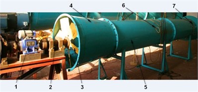
Table 3Comparison of simulation and experimental values
Mass flow rate | Static pressure | Overall sound pressure level | |
Non-smooth surface fan simulation value | 10 m3/s | 407 Pa | 95.5 dB |
Non-smooth surface fan experimental value | 10.17 m3/s | 412 Pa | 99.1 dB |
Arc bending plate fan experimental value | 10.28 m3/s | 422 Pa | 119.8 dB |
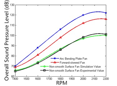
Fitting the noise speed curve of 3 fans at different speeds is as shown in Fig. 25. The figure illustrates that the simulation value and experiment value of the non-smooth surface fan deviation are small and verify the accuracy of the previous aero-acoustic simulation. Through comparing the noises rotational speed between these several fans, we can find that noises are directly proportional with the speed, and they will decrease with the increase of the speed. When the speed is higher enough, noises will be reduced significantly. In each speed, the noise from the non-smooth surface fan is lower than the arc slab fan. The different values are increasing with the growth of speed, which shows that the non-smooth surface fan is reducing noises obviously when the rotate speed is high.
Fig. 25Comparison of noise at different RPM
6. Conclusions
We combine the CFD flow field analysis with bench test to analyze features of the non-smooth surface cooling fan which could reduce noise strongly in some type of wheel loader, and find several characters: (1) The non-smooth surface fan is lower than the arc slab fan in mass flow rate and pressure drop, while it meets the requirements of heat exchange in power cabins; the novel fan could restrict the vortex between the cabin interior and air intake area, and the flow field of the air outlet is more stable. (2) In a certain rotate speed, the overall sound pressure level of the non-smooth surface fan reduces up to 20.9 % than the standard arc bending plate fan, and the max noises decrease by 21.5 %; through various rotate speeds test, we find that the non-smooth surface fan will be more effective to restrict the production of noises when it is in a high speed. When the mass flow rate losses in a narrow range, obviously, it will be more effective to reduce noises by the non-smooth surface fan, which widely provides a new mind in designing the large diameter fans in Off-Highway machinery.
References
-
Baliatsas C., et al. Health effects from low-frequency noise and infrasound in the general population: Is it time to listen? A systematic review of observational studies. Science of the Total Environment, Vols. 557-558, 2016, p. 163-169.
-
Pochkin Y., Khaletskiy Y. Aircraft fan noise reduction technology using leaned stator blades. Procedia Engineering, Vol. 106, 2015, p. 368-376.
-
Zenger F. J., et al. Experimental investigation of the noise emission of axial fans under distorted inflow conditions. Journal of Sound and Vibration, Vol. 383, 2016, p. 124-145.
-
Canepa E., et al. An experimental investigation on the tip leakage noise in axial-flow fans with rotating shroud. Journal of Sound and Vibration, Vol. 375, 2016, p. 115-131.
-
Lighthill M. J., Lighthill M. J. On sound generated aerodynamically. Proceedings of the Royal Society A Mathematical Physical and Engineering Sciences, Vol. 267, Issue 1329,1962.
-
Brooks T. F., Hodgson T. H. Trailing edge noise prediction from measured surface pressures. Journal of Sound and Vibration, Vol. 78, Issue 1, 1981, p. 69-117.
-
Tadamasa A., Zangeneh M. Numerical prediction of wind turbine noise. Renewable Energy, Vol. 7, Issue 36, 2011, p. 1902-1912.
-
Kalliadasis S., Ruyer Quil C., Scheid B., et al. Isothermal Case: Three-Dimensional Flow. Springer, London, 2012.
-
Brooks T. F., Marcolini M. A. Airfoil tip vortex formation noise. AIAA Journal, Vol. 2, Issue 24, 2015, p. 246-252.
-
Kusiak Andrew, Li W. The prediction and diagnosis of wind turbine faults. Renewable Energy, Vol. 1, Issue 36, 2011, p. 16-23.
-
González Javier Serrano, et al. Optimization of wind farm turbines layout using an evolutive algorithm. Renewable Energy, Vol. 35, 2010, p.1671-1681.
-
Brooks T. F., Marcolini M. A. Scaling of airfoil self-noise using measured flow parameters. AIAA Journal, Vol. 2, Issue 23, 1985, p. 207-213.
-
Yang Li, et al. Internal flow mechanism and experimental research of low pressure axial fan with forward-skewed blades. Journal of Hydrodynamics Ser. B, Vol. 20, Issue 3, 2008, p. 299-305.
-
Panigrahi Durga Charan, Mishra D. P. CFD simulations for the selection of an appropriate blade profile for improving energy efficiency in axial flow mine ventilation fans. Journal of Sustainable Mining, Vol. 13, Issue 1, 2014, p. 15-21.
-
Ffowcs Williams J. E., Hawkings, D. L. Sound generated by turbulence and surfaces in arbitrary motion. Philosophical Transactions of the Royal Society, Vol. A264, 1969, p. 321-342.
-
Ewert R., Schröder W. On the simulation of trailing edge noise with a hybrid LES/APE method. Journal of Sound and Vibration, Vol 27, 2004, p. 509-524.
-
Krishna S. R., Krishna A. R., Ramji K. Reduction of motor fan noise using CFD and CAA simulations. Applied Acoustics, Vol. 72, Issue 12, 2011, p. 982-992.
-
Ge Hai Wen, et al. PIV measurement and numerical simulation of fan-driven flow in a constant volume combustion vessel. Applied Thermal Engineering, Vol. 64, Issue 1-2, 2014, p. 19-31.
-
Pascu, Maria Axial Fan Design: Modern Layout and Design Strategy for Fan Performance Optimization. VDM Publishing, Saarbrücken, 2009.
About this article

The work reported in this paper is supported by the National Natural Science Foundation of China (Grant No. 50775096), and the National Key Technology Research and Development Program of the Ministry of Science and Technology of China (Grant No. 2013BAF07B04).
