Abstract
In order to solve existing problems of ballastless tracks, such as various kinds of internal damage and detection difficulties, this paper presents a method based on Gaussian curvature mode shapes. The proposed method has been validated according to relevant numerical simulations and laboratory tests (e.g. those performed for detecting interlayer damage of CRTS II plate-type ballastless tracks), and had led to the following conclusion: if no damage exists in ballastless tracks, the Gaussian curvature mode shapes will be smooth and continuous under different order modes of the track slabs and no obvious peaks will be found. According to the numerical simulation, in vertical and bending vibration modes of damaged track slabs (e.g. the second-, third-, fourth-, ninth- and tenth-order), the Gaussian curvature modes have obvious peaks at damaged locations; and the second-, third- and fourth-order Gaussian curvature modes of track slabs have discontinuity points at damaged locations according to the calculation made in the modal test for the scale model of damaged ballastless tracks. Moreover, the method based on Gaussian curvature mode shapes can be used for detecting and locating internal damage of ballastless tracks accurately.
1. Introduction
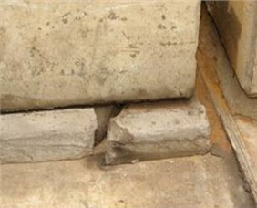
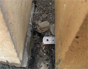
Ballastless tracks have become main track structures of high-speed railways in China due to their remarkable features of high smoothness, high stability, and low maintenance [1, 2]. As the base for the operation of high-speed trains, ballastless tracks are always exposed in various natural environments. Their main structures, which are made of reinforced concrete, always suffer from different kinds of damage [3-5]. This is attributable to long-term and continuous dynamic water pressure, temperature gradient, and trainload, as well as improper operation during construction and maintenance. Some damages, e.g. track slab spalling, cracks, CA mortar breakage, and others, occur on the external surfaces of ballastless track structures, as shown in Fig. 1. Their locations and types can be determined through visual observation and can be maintained or repaired separately and in time. In addition, for typical layer-like concrete structure, the internal and interlayer parts of the ballastless tracks are always susceptible to damage, such as internal holes, cracks, and interlayer open joints, which are difficult to detect directly. If not promptly handled, internal damages of ballastless tracks that occur during the operation of high-speed railways will certainly affect the safe operation of high-speed trains [6, 7]. However, detection methods for internal damage of ballastless tracks have been thus far never provided in the world.
Important published papers on damage identification in concrete structures in the past were reviewed. Pandey proposed that structural damage be identified and located through a curvature mode, and conducted a study through a cantilever-supported beam analysis model. According to the results, the area of the curvature mode changes with the enlargement of the damaged area and the structural damage area can be detected by way of the curvature mode [8]. Wahab detected damage of prestressed concrete bridges according to the changing curvature mode, verified results through several continuous beam models with different damage locations, and put forward the concept of the curvature damage factor [9]. For those bending structures, such as bridges and others, D. B. Li studied the relationship between the curvature mode and the strain mode, explained the theoretical basis and characteristics regarding the curvature mode analysis, deducted the test method and parameter identification of the curvature mode, and introduced the application of the curvature mode in detecting structural damage [10]. G. Y. Li performed a structural displacement mode analysis and curvature mode analysis on cantilever beams with different kinds of damage, discovered that the curvature mode method can be adopted to diagnose the location and extent of damage accurately, and put forward the amplitude variation coefficient of the curvature mode, which has a good linear dependence with the extent of structural damage [11]. Maia established a simplified beam mode and made a comparative study on the difference among the modal vibration mode, the slope of the modal vibration mode, the modal curvature, the modal quadratic curvature, and the damage index in detecting structural damage [12]. G. Q. Li studied how to detect damage of slabs (elastic thin slabs simply supported on four sides) according to the vibration mode curvature of the displacement, and pointed out that the damage of the slabs can only be detected and located, and the damage extent, evaluated according to the structural vibration curvature by setting enough detecting points of the vibration mode [13]. K. Y. Zhang summarized existing methods for identifying structural damage, and, by taking a cantilever beam structure with damage as an example, he performed a comparative analysis on three methods (i.e., the displacement mode, the displacement mode difference, and the curvature mode), and found that the curvature mode method is obviously better than the displacement mode method and can identify and locate structural damage effectively in addition to the extent of damage [14]. Choi proposed that structural damage be detected and located by way of changing modal distribution obtained according to modal distribution ranges (formed before and after being damaged) of the structure, put forward the expression of damage indices based on bending curvatures and invariant moments and ultimately verified the feasibility of the mentioned method through numerical simulation and indoor experiment [15]. By taking the 2D frame finite element model as an example, J. Chen studied the application of curvatures in identifying the damage of bridges and continuous beam structures, and performed a comparative analysis on the influence of vibration mode order, the extent of structural damage, and the detection of points when identifying damage [16]. Chandrashekhar put forward a damage detection method based on a fuzzy logic method, and studied the uncertain damage factor distribution of the cone cantilever beam curvature mode based on the Monte-Carlo method in order to handle errors caused by the structural shape and measuring method. The mentioned method can be adopted to detect one or more kinds of structural damage accurately [17]. Dawari detected and located honeycomb damage of a prestressed concrete beam model with a modal curvature and modal flexibility difference based method, performed an eigenvalue analysis on the finite element model of prestressed concrete beams in order to verify the calculation method and calculated eigenvector under different conditions and consider such damage as belonging to the reduction of local structural rigidity [18]. Ciambella studied a method for detecting changing rigidity locations of damaged beams through the curvature mode. To locate structural damage effectively, a perturbation method regarding Euler-Bernoulli’s equation has been developed, which can be adopted to detect sizes of different areas and various kinds of structural damage [19]. Dessi performed a comparative analysis on several methods for identifying damage through a curvature mode. The studied subjects were all Euler-Bernoulli models with damage. The structural damage was simulated through positioning and equivalent rigidity reduction. The difference among different methods in identifying the location of damage, the extent of damage, and the range of damage were mainly studied [20]. Furthermore, modal analysis is applied to study the vibration Behaviors of the microbeams and their ensembles. Yayli proposed a finite element procedure for computation of natural frequencies for the microbeams of constant width and linear varying depth, based on strain gradient elasticity theory [21]. Also, the free axial vibration response of single-walled carbon nanotubes (SWCNTs) and carbon nanotubes (CNTs) with arbitrary boundary conditions is studied based on the non-local elasticity theory, and the effects of spring parameters on the vibration frequencies are discussed in detail [22-23].
Internal damages of ballastless tracks, e.g. honeycomb damage, cracks, interlayer open joints, and others, can cause the change of kinetic and modal parameters of whole structures [24-25], and accordingly, leading to a decrease of rigidity and increase of flexibility for the physical state as well as a drop of fixed frequency, rise of dampness, and change of the vibration mode for the modal state. Therefore, by referencing such methods for detecting damage of concrete structures, A method for detecting internal damage of ballastless tracks is presented based on Gaussian curvature mode shapes, and the Gaussian curvature mode adopted in this paper is in fact a second derivative of the structural vibration mode, which means it is more sensitive to structural damage as compared to the vibration mode. Moreover, its theoretical basis is complete for realizing higher accuracy in damage identification.
Fig. 1Damages of ballastless tracks
2. Damage identification methods
Mode shapes are fixed vibration characteristics of the structural system. Each order mode of the system has its own fixed frequency, modal vibration mode, and damping ratio. Through numerical simulation or laboratory test, i.e. the modal analysis, these parameters can be obtained. In the modal analysis, the vibration system, with multiple degrees of freedom established by physical coordinates and through coordinate transformation decoupling, can be used to establish a modal coordinate equation in order to calculate the eigenvalue of the system. Basis vectors of the coordinate system form the modal vibration mode of the system, which reflect the basic fixed dynamic equilibrium of their deformation energy when the structure vibrates under an undamped condition. This situation can meet the equilibrium condition and consistency condition among particles. Different equilibrium states can appear separately and do not depend on each other, avoiding coupling among different modes, namely orthogonality among different modes. Only basis vector systems with basis vectors being orthogonal to each other can form a coordinate system. Although different fixed modes do not couple each other, the response can be expressed as the sum of all modes, which reflects the modal superposition. Since displacements reflect the superposed variables of displacement vibration modes and are all global variables just like fixed frequencies, it is difficult to reflect local structural damage.
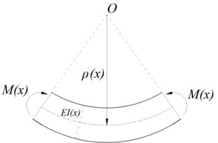
Curvature modes are special deformation modes generated during bending vibration, which can be obtained through the displacement mode and are sensitive to local changing sizes and internal damage of structures [26]. Taking an elastic beam as an example, the modal curvature at one section of the elastic beam (Fig. 2) can be expressed as the Eq. (1), which is based on the material mechanics:
where refers to the bending rigidity at of the section. Local structural damage can cause a drop of local rigidity (), leading to a curvature increase of the local structural damage area and discontinuity of the curvature mode’s vibration values, so the damage can be diagnosed by analyzing the vibration discontinuity of the curvature mode. Usually, curvature mode shape cannot be directly measured or calculated. But curvature mode shape can be obtained and calculated approximately by center difference method based on the displacement modal vibration mode. According to the vibration mode analysis on the discrete model of structural finite elements, if the vibration of the displacement mode at nodes of equispaced discrete units of finite elements can be calculated, the vibration of the structural curvature mode will be obtained according to the central difference method, as shown in Eq. (2):
where refers to the vibration amplitude of order , refers to the number of the node to be calculated, refers to the space between the nodes.
Fig. 2Relation between moment and curvature
Curvature modes are very sensitive to system damage. If any damage appears in the structural system, the curvature mode shapes of the system will discontinue, however, which reflect a piece of information in one direction of the system mainly. For ballastless tracks, the structural system relates to the curvature mode in two directions. In order to show the change of the curvature mode shapes regarding ballastless track structures clearly and identify damage of the ballastless track, this paper introduces the damage identification method based on Gaussian curvature mode shapes with an analysis on the curvature mode of the ballastless track structure.
The following shows the calculation method of the Gaussian curvature mode. Curved surfaces have two elemental forms, namely the first and second elemental forms. The arc lengths of curved surfaces, the angle between two directions and the area of the curved surfaces can be calculated according to the first form. The shapes of the curved surfaces may be different from each other apparently even though the first elemental forms are the same, indicating that the first elemental forms of curved surfaces cannot be used to reflect the shape of curved surfaces separately and completely without the second elemental form.
Supposing that is a curved surface of one space and is a plane, then the vector function in the Eq. (3) will be:
If indicates that plane corresponds with the points of curved surface , it is considered that is the parametric representation of curved surface . Where is the coordinate of point of the curved surface, is the end of the radius vector .
Any point of the curved surface has at least two directions, the corresponding normal curvatures of which are called principal curvatures. The two directions being perpendicular and conjugate to each other on curved surface are called principal directions, the corresponding normal curvatures of which are called the principal curvatures of the curved surface. Where the principal curvature () of any point is the solution of the following Eq. (4):
where , and stand for the first fundamental quantity, , and stand for the second fundamental quantity.
Supposing that and are two principal curvatures of any point of the curved surface, their product () is called the Gaussian curvature of the curved surface at this point, which can be expressed by , as shown in the Eq. (5):
Normal curvatures and principal curvatures are in relation to the selection of a unit of normal vectors of the curved surface; however, the Gaussian curvature does not change with the change of normal vectors.
Curvature mode values of two directions (, ) will be involved in calculating the curvature modes of track slabs. According to differential geometry, Gaussian curvatures can be adopted to reflect the curvatures of plate-type structures in two directions comprehensively. Supposing that the two principal curvatures of any point on a vibration mode surface [, , ] are and , the Gaussian curvatures can be obtained according to the Eq. (5).
3. Numerical simulations
In order to study the feasibility of identifying structural damage of ballastless tracks based on Gaussian curvature mode shapes, by taking CRTS II plate-type ballastless track as an example, a modal analysis was made for the structural system. The Gaussian curvatures of the track slab under different order modes was calculated according to the Gaussian curvature theory after the vibration displacement results regarding the track slab of the ballastless track system under different order modes were calculated. Damage of ballastless tracks was detected by making a comparison with Gaussian curvature mode shapes of track slabs without damage.
3.1. Establishment of numerical model
Interlayer damages of a CRTS II plate-type ballastless track, namely CA mortar damage, open joints, and splitting between track slab and mortar layer, are studied in this paper. The finite element software ANSYS is adopted for establishing the numerical model. Since the supporting layers of the plate-type ballastless track structure are attached vertically, the change of vibration for which is minor in relation to that for the track slabs. In order to simplify the calculation, only a track slab-CA mortar model is established. Considering the function in the track structure, the CA mortar and track slab are simulated through the Combin-14 spring element and Shell 63 element, respectively. The interlayer damage of the ballastless track is simulated by removing spring units or deducting spring rigidity. The parameters of the track slab are as follows: the elastic modulus is 3.65e10 Pa, the density is 2,500 kg/m3, and Poisson’s ratio is 0.2. The parameters of the CA mortar are as follows: the elastic modulus is 3e8 Pa, the length of the track slab is 4.8 m, and the width of the track slab is 2.4 m. The finite element model is divided into 12 parts transversely and 24 parts longitudinally. In the numerical simulation, the supposed damage of the CA mortar are 1.0 to 1.4 m in the track slab coordinate system in the directions of and , and the splitting area is 0.16 m2. For vertically attached plate-type track slabs, both ends are restricted by the adjacent slabs, so both ends of the track slab and mortar are restricted completely. Considering the practical situation, the track slab is also restricted transversely in order to restrict transverse displacement, as shown in Fig. 3.
Fig. 3The simulated model for interlayer damage of the ballastless track
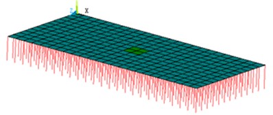
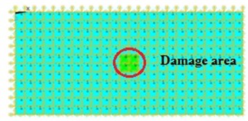
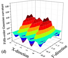
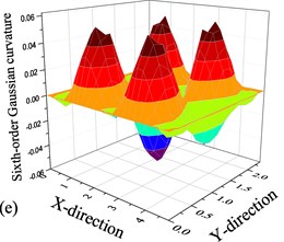
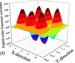
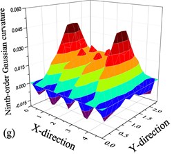
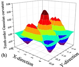
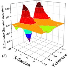
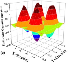
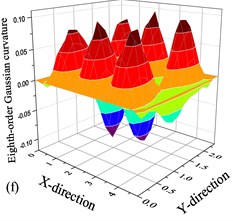
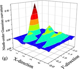
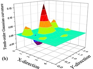
Fig. 4the Gaussian curvature mode shapes of damage-free track slab: a) Second-order Gaussian curvature mode shape, b) Third-order Gaussian curvature mode shape, c) Fourth-order Gaussian curvature mode shape, d) Fifth-order Gaussian curvature mode shape, e) Sixth-order Gaussian curvature mode shape, f) Eighth-order Gaussian curvature mode shape, g) Ninth-order Gaussian curvature mode shape, h) Tenth-order Gaussian curvature mode shape
3.2. Simulation results
3.2.1. Ballastless track system without damage
In this paper, a finite element model of a damage-free track slab-CA mortar system is established. The track slabs mainly suffered from bending vibration. In general, if the Gaussian curvature method is used to identify damage, the calculated Gaussian curvature of an order will be adopted; however, considering the vibration mode at the damaged part may happen at a piece of pitch line of a certain order mode, the change of which might be covered by the vibration of this order mode. According to the modal analysis on the ballastless track system, for the first 10 vibration modes of track slabs: the first and seventh orders only related to longitudinal vibration and the vertical modal displacement is 0 mm; the second, third, fourth, ninth, and tenth orders mainly related to vertical bending vibration; and the fifth, sixth, and eighth orders related to twisting vibration. Since interlayer damage of ballastless tracks can cause change of vertical supporting rigidity in the system directly, the Gaussian curvature values of different orders for the first 10 vibration modes of track slabs are calculated, except for the first and seventh order (Fig. 4).
According to the calculated Gaussian curvature mode shapes of different order (Fig. 4), the surfaces of the Gaussian curvature are smooth and distributed symmetrically and no obvious peaks appeared. This indicates that in the track slab-CA mortar system, there is neither curvature discontinuity nor rigidity discontinuity in the units. In other words, no damage of the track slab-CA mortar system is found. It can be used to identify the internal damage in ballastless tracks.
3.2.2. Ballastless track system with damage
The computational model is modified according to the set damage of the ballastless track system, and the supporting spring at the location with damage is removed. The displacement vibration mode of the track slab is also analyzed. Then, the damaged track slab’s distribution of the Gaussian curvature mode is calculated according to the Gaussian curvature theory. The calculated results are as shown (Fig. 5).
Fig. 5The Gaussian curvature mode shapes for track slab set with damage: a) Second-order Gaussian curvature mode shape, b) Third-order Gaussian curvature mode shape, c) Fourth-order Gaussian curvature mode shape, d) Fifth-order Gaussian curvature mode shape, e) Sixth-order Gaussian curvature mode shape, f) Eighth-order Gaussian curvature mode shape, g) Ninth-order Gaussian curvature mode shape, h) Tenth-order Gaussian curvature mode shape
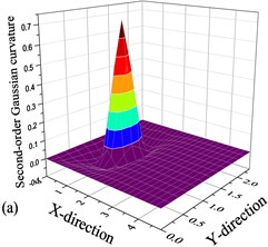
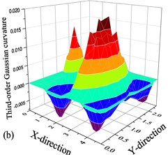
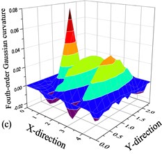
In second-order Gaussian curvature, an obvious peak appeared, indicating that curvature discontinuity occurs in this area (Fig. 5). When splitting occurs in CA mortar, a track slab’s lower supporting condition changes. For the track slab-CA mortar system, local splitting of CA mortar can cause local rigidity discontinuity of the system. According to material mechanics, the change of rigidity can cause a change of curvatures. Therefore, the area with damage can be detected according to the discontinuity location of the second-order Gaussian curvature. For the calculated third-, fourth-, ninth- and tenth-order Gaussian curvatures, an obvious peak appears at the same location. This clearly indicates that rigidity discontinuity occurs here, and the damaged area can be accurately identified. But for the calculated fifth-, sixth- and eighth-order Gaussian curvature, no obvious peak and change of curvatures appear. The three order Gaussian curvatures relate to twisting vibration, when the damage appears at the nodel line, the modes of vibration and Gaussian curvatures do not change, so the three order Gaussian curvatures cannot be used to identify the damaged area.
The vibration mode of vertical bending is better for identifying any single splitting of the plate-type ballastless track system. The splitting and its approximate range can be evaluated and detected according to the calculated second-, third-, fourth-, ninth- and tenth-order Gaussian curvatures.
4. Modal test
According to the calculated results for identifying damage of the ballastless track, the Gaussian curvature analysis on the vibration mode of the vertical bending for the track slab can help to identify the area where the damage exists accurately. A corresponding scale model of the ballastless track is made in order to verify the feasibility of the numerical simulation, and the damage of the ballastless track can be identified through laboratory test.
The curvature modal test is mainly performed for ballastless tracks. Therefore, a certain number of acceleration sensors are first placed at a certain place on the track slab. The instrument used for the test system comprised of an excitation device and a detection device. The track slab is then exerted with a certain transient force by a hammer, and the vibration signals of the sample are detected by acceleration sensors. Next, these signals are sent to a signal collection system after being amplified by an amplifier. The vibration displacement values of different testing points under different order modes can be selected according to the modal analysis on the acceleration for the time domain data of the testing points measured on the track slab.
4.1. Test method
To verify the accuracy of the Gaussian curvature method in identifying damage of ballastless tracks, a plate-type ballastless track model is made (Fig. 6). The size of the track slab is 1.2 m×0.8 m×0.19 m. The C40 concrete is used, and the density of which is 2,500 kg/m3. The size and density of the CA mortar is 1.2 m×0.8 m×0.03 m and 1,548 kg/m3, respectively. During the manufacture of the sample, splitting and open joints are preset respectively in the ballastless track structure. The range of the damage is 0.4 m×0.4 m and the positions of collocation points are shown in Fig. 7.
The DH5922 (Donghua) dynamic signal collection system is used mainly in this test. A hammer is also used as the excitation device, and the force-hammer is used to apply transient signals to the track slab model by the hammer percussion. The force signal and response signal of the tested object can be measured at the same time. The pulse force and impact waveform depends on material hardness of the force-hammer’s top. If the material hardness is higher, the duration time of impact force is shorter and frequency component is higher.
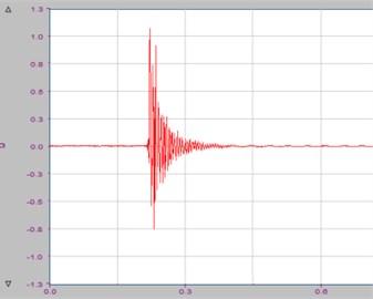
The sampling frequency in the test is 51.2 kHz; the analytical frequency in the study is 0-3 kHz, the vibration acceleration signal and noise signal are collected and transferred to the testing computer through the charge-amplifier and signal collection board. The linear smoothing method is adopted for smoothing the measured data. The vibration acceleration responses of the track slab model are collected at different testing points. The input signal in the test is a pulse excitation signal, and the force window is applied to remove the noise signal. The collected signals are the damped vibration signals, and the exponential window is applied to make the signals attenuating to 0 at the end of the signals and eliminate the truncation errors. The maximum excitation force is 11.435 kN, and the time-history curve of excitation force is shown as Fig. 8.
Fig. 6Model of ballastless track
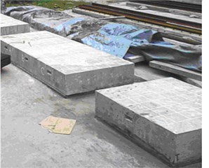
Fig. 7Modal test system for detecting damage
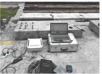
Modal test signals are collected by piezoelectric-type acceleration sensors placed on the track slab. The excited and responded process is recorded by the DH5922 (Donghua) dynamic signal collection system. The recorded time domain signals are converted into digital number signals by an A/D converter. The acceleration sensors are placed evenly on the track slab. The longitudinal and transverse spaces among the testing points are 0.2 m and 0.16 m, respectively. The modal test of the track slab is performed by means of single-point excitation and multi-point vibration signal collection. The testing system is powered after the acceleration sensors were installed. With a proper wire connection, the modal test is performed after normal signals were sent. The hammer is used for giving excitation signals at different testing points, and the data collection system is used for collecting time domain signals under different conditions (Fig. 9).
Fig. 8Pulse force time domain signals
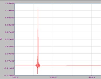
Fig. 9Acceleration time domain signals
The acceleration signals and force signals are processed for wave filtration and noise reduction before making a modal analysis on the tested data. A structural model corresponding with the test sample is established in the modal analysis software, and nodes corresponding with the testing points are given in the model. The frequency response functions of each testing point are calculated first according to the dynamometry. This test is carried out using single-point excitation and multi-point collection. Therefore, taking one testing point as an example, the frequency response function can be calculated. Different order vibrations of the ballastless track system can be calculated through the modal analysis software after the frequency response function is calculated.
4.2. Results analysis
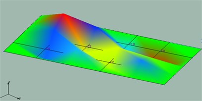
For the acceleration time domain signals of testing points, grounding technique is applied to reduce the noise in the testing process and moving average filtering algorithm is applied to eliminate the noise in the signal processing stage. The simulated model consistent with the testing model of ballastless track is established and the data collection points are placed at the corresponding nodes. The modal test is performed with the method of single point excitation and multiple-point collection. Frequency response function of each collection point is simulated with the approach of force-testing (Fig. 10) and the vibration modes of ballastless track system are obtained by the modal analysis software, the second order vibration mode of track slab is taken as example and shown in Fig. 11.
Fig. 10Frequency response function
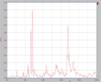
Fig. 11The second order vibration mode of track slab
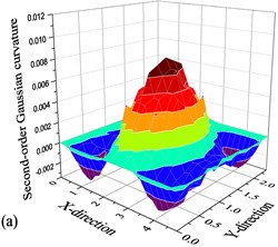
The Gaussian curvature mode shapes of the track slab are calculated through the central difference method with the vibration mode displacement. The second-order Gaussian curvature mode shape of test model is taken as example and shown in Fig. 12. The Gaussian curvature mode is simulated based on the actual test data in Fig. 12(a) and it is simulated based on the increased data by the linear interpolation between two adjacent collocation points in Fig. 12(b).
Fig. 12The second-order Gaussian curvature mode shapes of test model: a) Simulated based on the actual test data, b) Simulated based on the increased data by the linear interpolation between two adjacent collocation points
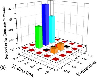
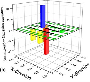
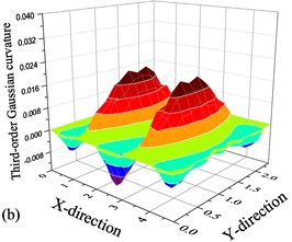
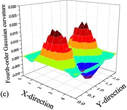
A peak appeared in the second-order Gaussian curvature of the track slab (-direction coordinate: 0.2-0.4 m, -direction coordinate: 0.3-0.6 m), so damage can be found in this area (Fig. 12(a)). This measured result is almost the same as that of the practical test, indicating high detection accuracy. While a peak appeared in the second-order Gaussian curvature of the track slab (-direction coordinate: 0.3 m, -direction coordinate: 0.3-0.4 m), the measured result is different from that of the practical test and it has some errors for the linear interpolation between two adjacent collocation points. The third- and fourth- order vibration modes of the track slab are also simulated based on the actual test data, as shown in Fig. 13.
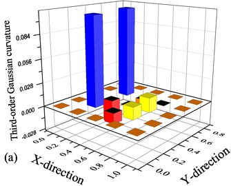
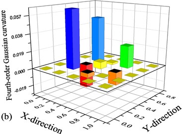
According to the tested results of the third- and fourth -order Gaussian curvature, an obvious peak appears under the two order modes (-direction coordinate: 0.2-0.6 m and -direction coordinate: 0.2-0.6 m), indicating that curvature discontinuity occurs in this area. The change of the curvature is caused by a change of rigidity, and therefore damage appeared here. Accordingly, this is found to be correct as compared with the ones actually preset.
Fig. 13Test results for the Gaussian curvature mode of the ballastless track: a) Third-order Gaussian curvature mode shape, b) Fourth-order Gaussian curvature mode shape
5. Conclusions
By taking the detection of the interlayer damage of CRTS II plate-type ballastless track in China as an example, this paper presents a method for detecting damage of an ballastless track system based on Gaussian curvature mode shapes. The proposed method has been proved feasible according to the relevant numerical simulation and laboratory test, and the main conclusions constitute the following:
1) If no damage is found in the ballastless track, the Gaussian curvature mode shapes will be smooth, continuous, and symmetrical to each other under different order modes of the track slabs. In addition, no obvious peaks will be found. Thus, if no curvature discontinuity is found, no damage will appear in the ballastless track.
2) Taking the detection of the interlayer damage of CRTS II plate-type ballastless tracks as an example, the vertical bending vibration modes (e.g. the second-, third-, fourth-, ninth- and tenth-order), and according to the calculation for different order Gaussian curvature modes of damaged track slabs, obvious peaks will appear at locations with damage. Therefore, the feasibility of detecting internal damage of ballastless tracks through Gaussian curvature modes has been proved theoretically.
3) Second-, third-, and Fourth-order Gaussian curvature modes are calculated according to the Gaussian curvature theory through the modal test for the scale model of ballastless track with damage. Discontinuity points are found in all order Gaussian curvature modes, and the locations of which are almost the same as those with preset damage.
4) The damage detection method based on a Gaussian curvature mode, can be adopted to detect and roughly locate internal damage of ballastless tracks.
References
-
Wang P., Xu H., Chen R., Xu J., Zeng X. Experimental research on compression properties of cement asphalt mortar due to drying and wetting cycle. Advances in Materials Science and Engineering, Vol. 12, Issue 2014, 2014, p. 1-6.
-
Ren J., Wang P., Yang R. Slab upwarping of twin-block slab track on subgrade-bridge transition section: parameter study and repair method. Journal of the Transportation Research Board, No. 2448, Transportation Research Board of the National Academies, Washington, D.C., 2014, p. 115-124.
-
Wang P., Ren J., Xiang R., Liu X. Influence of rub-plate length on forces and displacements of longitudinally coupled slab track for a bridge turnout. Proceedings of the Institution of Mechanical Engineers Part F: Journal of Rail and Rapid Transit. Vol. 226, Issue 3, 2012, p. 284-293.
-
Zhu S., Fu Q., Cai C., Spanos P. Damage evolution and dynamic response of cement asphalt mortar layer of slab track under vehicle dynamic load. Science China: Technological Sciences, Vol. 57, Issue 10, 2014, p. 1883-1894.
-
Chen R., Wang P., Wei X. Manufacturing Process of cement asphalt mortar and its applications on slab track. Journal of Nanoelectronics and Optoelectronics, Vol. 7, Issue 2, 2012, p. 155-161.
-
Esveld C. Recent development in slab track. European Railway Review, Vol. 9, Issue 2, 2003, p. 81-85.
-
Katuoshi A. Development of slab track for hokuriku shinkansen line. Quarterly Report of RTRI, Vol. 42, Issue 1, 2001, p. 35-41.
-
Pandey A. K., Biswas M., Samman M. Damage detection from changes in curvature mode shapes. Journal of Sound and Vibration, Vol. 145, Issue 2, 1991, p. 321-332.
-
Wahab M. M. A., Roeck G. D. Damage detection in bridge using modal curvatures: application to a real damage scenario. Journal of Sound and Vibration, Vol. 226, Issue 2, 1999, p. 217-235.
-
Li D., Lu Q., Qin Q. Curvature modal analysis for bending structures. Journal of Tsinghua University (Science and Technology), Vol. 42, Issue 2, 2002, p. 224-227, (in Chinese).
-
Li G., Zheng H. Studies on curvature modal analysis of damage structures. Journal of Vibration, Measurement and Diagnosis, Vol. 22, Issue 2, 2002, p. 136-152, (in Chinese).
-
Maia N. M. M., Silva J. M. M., Almas E. A. M. Damage detection in structures: from mode shape to frequency response function methods. Mechanical System and Signal Processing, Vol. 17, Issue 3, 2003, p. 489-498.
-
Li G., Liang Y. Dynamic damage detection of plate-like structure using curvature mode shapes. Journal of Vibration, Measurement and Diagnosis, Vol. 24, Issue 2, 2004, p. 111-116, (in Chinese).
-
Zhang K., Sun Z., Zou X., Xue G., Zhang B. Curvature mode technique of damage identification for beam bridge structure. Journal of Wuhan University of Technology (Transportation Science and Engineering), Vol. 28, Issue 6, 2004, p. 855-858, (in Chinese).
-
Choi S., Park S., Yoon S., Stubbs N. Nondestructive damage identification in plate structures using changes in modal compliance. NDT&E International, Vol. 38, Issue 7, 2005, p. 529-540.
-
Chen J., Xiong F. Curvature mode shapes-based damage identification method. Journal of Wuhan University of Technology, Vol. 29, Issue 3, 2007, p. 99-102, (in Chinese).
-
Chandrashekhar M., Gunguli R. Damage assessment of structures with uncertainty by using mode-shape curvatures and fuzzy logic. Journal of Sound and Vibration, Vol. 326, Issues 3-5, 2009, p. 939-957.
-
Dawari V. B., Vesmawala G. R. Modal curvature and modal flexibility methods for honeycomb damage identification in reinforced concrete beams. Procedia Engineering, Vol. 51, 2013, p. 119-124.
-
Ciambella J., Vestroni F. The use of modal curvatures for damage localization in beam-type structures. Journal of Sound and Vibration, Vol. 340, Issue 3, 2015, p. 126-137.
-
Dessi D., Camerlengo G. Damage identification techniques via modal curvature analysis: overview and comparison. Mechanical System and Signal Processing, Vol. 52, Issues 53-2, 2003, p. 181-205.
-
Yayli M. Ö. Free vibration behavior of a gradient elastic beam with varying cross section. Shock and Vibration, Vol. 2014, 2014, p. 1-11.
-
Yayli M. Ö. On the axial vibration of carbon nanotubes with different boundary conditions. Micro and Nano Letters, Vol. 9, Issue 11, 2014, p. 807-811.
-
Yayli M. Ö. A compact analytical method for vibration analysis of single-walled carbon nantubes with restrained boundary conditions. Journal of Vibration and Control, Vol. 22, Issue 10, 2016, p. 2542-2555.
-
Lei X., Zhang B. Analysis of dynamic behavior for slab track of high-speed railway based on vehicle and track elements. Journal of Transportation Engineering, Vol. 137, Issue 4, 2011, p. 227-240.
-
Zhu S., Cai C. Interface damage and its effect on vibrations of slab track under temperature and vehicle dynamic loads. International Journal of Non-linear Mechanic, Vol. 58, Issue 10, 2014, p. 222-232.
-
Cao M., Radzienski M., Xu W., Ostachowicz W. Identification of multiple damage in beams based on robust curvature mode shapes. Mechanical System and Signal Processing, Vol. 546, Issue 2, 2014, p. 468-480.
Cited by
About this article

The present work has been supported by the Project (51378439 and 51608459) of the National Natural Science Foundation of China and the Project (51425804) of the National Science Fund for Distinguished Young Scholars of China.
Each author has made substantive intellectual contributions to all three of the following categories: substantial contributions to conception and design, or acquisition of data, or analysis of data; drafting the article or revising it critically for important intellectual content; and final approval of the version to be published. Guarantor of integrity of entire study: Jingmang Xu. Study concepts: Jingmang Xu, Ping Wang, Rong Chen. Study design: Jingmang Xu, Rong Chen. Literature research: Jingmang Xu, Ping Wang. Experimental studies: Jingmang Xu, Hao Liu, Zhipeng Hu. Data acquisition: Hao Liu, Zhipeng Hu. Data analysis/interpretation: Jingmang Xu, Hao Liu. Manuscript preparation: Jingmang Xu. Manuscript definition of intellectual content: Jingmang Xu, Rong Chen. Manuscript editing: Jingmang Xu. Manuscript revision/review: Jingmang Xu, Rong Chen. Manuscript final version approval: Jingmang Xu.
