Abstract
The finite element model of wheels without holes was established to compute its free modal and compare with the experimental result. The relative error was controlled within 5 %, which indicated that the finite element model in this paper was reliable. Based on the finite element and geometric model, the acoustic boundary element model of wheels was established to compute the radiation noise of wheels under the action of radial and normal excitation forces. Results showed that the change trend and value of radiation noises of wheels were similar under the action of two kinds of excitation forces when the analyzed frequency was lower than 1421 Hz. However, the radiation noise of wheels under the action of two kinds of excitation forces was significantly different and presented obvious directivity in three planes with the increase of the analyzed frequency. Then, models of wheels with 5, 6, 9 and ellipse holes were established to compute radiation noises and conduct comparative analysis. Results showed that the radiation noise of wheels with 6 holes was relatively minimum under radial and normal excitations and did not decrease with the increase of the hole number. The radiation noise of wheels with circular holes made certain improvement, compared with the radiation noise of wheels with ellipse holes. Distribution curves for the directivity of radiation noises of various wheels were highly symmetrical in the plane and radiation noises had relatively maximum in the position of multiples of 30°. The curve for the directivity of radiation noises of wheels with 5 holes was clearly different from that of other structures in the plane.
1. Introduction
Due to different generation mechanisms and parts, railway noise can be roughly divided into locomotive traction noise, accessory equipment noise, wheel-rail noise and aerodynamic noise. When train speed is between 250 km/h and 300 km/h, wheel-rail noise is the main noise source of the train. According to generation mechanism, wheel-rail noise can be classified into rolling noise, impulsive noise and howling [1]. Impulsive noise refers to the noise radiated from the vibration of wheel-rail system excited by the partial surface of wheel rail discontinuously. Howling refers to a kind of high-pitched noise made by the partial cross sliding of wheels along steel rails when vehicles operate in a small-radius curve. Rolling noise is caused by the vibration of wheel-rail system excited by the unsmooth surface of wheel rail and spread by air to surroundings [2]. Impulsive noise will be greatly reduced ever since long-rail seamless tracks and scientific grinding means are adopted. At present, howling is mainly restrained through increasing the contact friction force of wheel rail and preventing cross sliding. Limited by the current manufacturing level, rolling noise is unavoidable and can only be reduced through adopting certain measures.
Currently, a number of related studies have been conducted on the rolling noise of wheels. Thompson [3] deeply studied the proportion of respective noise radiation of wheels and steel rails and conducted theoretical analysis and experimental tests to show that wheels and steel rails made different contributions to wheel-rail rolling noise in different frequency ranges. Thompson [4] applied two-bit boundary element method to compute the influence of wheel diameter, web plate and hub thickness on the acoustic radiation efficiency and directivity of wheels. After carrying on long-term research into wheel shape [5], German scientific research institutions found that the radiation noise of wheels was affected by the web plate form and rolling circle diameter of wheels, transition arc curvature among web plate, rim and hub as well as the thickness of web plate and designed improved-type low-noise wheels according to experimental results. Based on the method of experimental test, Sato [6] studied the vibro-acoustic characteristics of wavy and straight web plate wheels. Further, he applied the method of combining finite element with boundary element to study the acoustic radiation characteristics of different parts of wheels and their proportions in the whole acoustic radiation of wheels [7]. Efthimeros [8] aimed to minimize the radiation noise of wheels based on genetic algorithm and conducted optimization design for the geometric shape of railway wheels. Nielsen [9] applied the experimental design method of multi-objective optimization and carried out optimization design for geometric parameters including wheel diameter, web plate thickness, lateral deviation between hubs, transition arc between rim and web plate as well as transition arc between web plate and hub so as to reduce the weight of wheels and decrease the rolling noise of wheels. Liu [10] conducted a study on the influence of parameter change of wheels on wheel-rail noise according to existing noise prediction models. The analysis showed that wheel-rail noise could be decreased through appropriately reducing wheel diameter and increasing the thickness of wheel web plates and quality of wheel treads. Fang [11] also made a comparison on the noise radiation of wheels with three forms of web plates, found straight web plate wheels possessed better radiation noise characteristics and got the result according with existing theoretical research.
At present, the methods of reducing unsprung weight like hollow axles and opening web plate holes are usually adopted in order to lower the dynamic action of wheel-rail contact. In addition, the web plate of wheels has large area and is the main sound source of noise radiation. Therefore, opening web plate holes cannot only lead to “acoustic short circuit”, but also reduce the radiating area of wheels and lower the noise radiation of wheels. Documents [12] theoretically explained that opening holes in wheel web plates could lead to “acoustic short circuit” and thus reduce noise radiation. However, documents did not deeply study the influence of form and number of wheel web plate holes on the characteristics of wheels like inherent frequency, acoustic radiation efficiency and acoustic radiation directivity.
This paper adopted finite element and boundary element hybrid method to compute and analyze the influence of form and number of wheel web plate holes on wheels’ acoustic radiation characteristics in detail, gave the acoustic radiation power and directivity of wheels under the action of unit normal and radial forces and provided certain reference for the performance design of NVH.
2. Finite element model
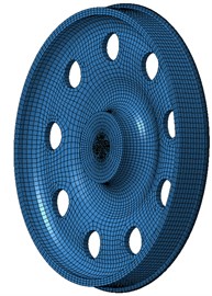
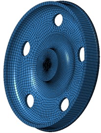
The geometric model of wheels was shown in Fig. 1(a). The model was a highly symmetrical structure. Circular holes of the model were used for installing axles. Fig. 1(b) was the section of wheels. As shown in the figure, the wheel was an S-shaped structure to efficiently reduce the vibration from high-speed trains and tracks. Based on the geometric model, the chamfer was simplified, cleaned and divided into hexahedral mesh. The element size of mesh was 10 mm. Finite element software Ansys and 3D solid element were applied to disperse the wheel and establish the three-dimensional finite element model of wheels without holes as shown in Fig. 1(c). The model contained 2301 elements and 2593 nodes. Suppose wheel web plate holes had no influence on the strength and reliability of wheels in the process of establishing finite element model. Wheel diameter was 840 mm; thickness was 25 mm; web plate was S-shaped; the elasticity modulus of wheel material was 210 GPa; density was 7.8e3 kg/m3; Poisson’s ratio was 0.3. The free modal of wheels was computed based on the finite element model.
Wheels were a composite structure and finite element model was relatively complex. Therefore, it was necessary to verify the finite element model through experiments to ensure the reliability of the subsequent analysis. Fig. 2 was an experiment on the free modal of wheels. The experiment was conducted in a semi-anechoic chamber for preventing that the secondary vibration caused by the reflection of vibration noises had an influence on the experimental result. The wheel was hung by a soft rope to simulate the free state of wheels. Then, 2 three-direction acceleration sensors were pasted on the wheel web plate. Wheel web plate, tread and rim were excited respectively by exciting hammer. Multi-channel data acquisition instrument was used to obtain the signal of acceleration sensors. Later, the tested signal was imported into computer for post-processing to obtain the free modal of wheel. Experimental modal was compared with finite element calculation result, which was shown in Table 1. In the table, R referred to radial modal while N represented normal modal. As displayed from Table 1, the relative error of experimental modal and calculating modal was small, which indicated that the finite element model of wheel established by this paper was reliable.
Fig. 1Geometric model and finite element model of wheels
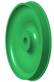
a) Geometric model
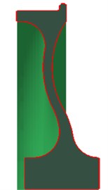
b) Section shape
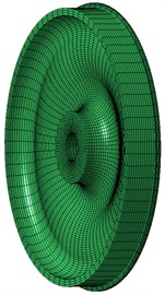
c) Finite element model
Fig. 2Free modal test of wheels
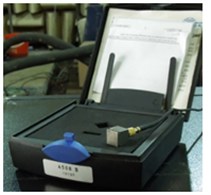
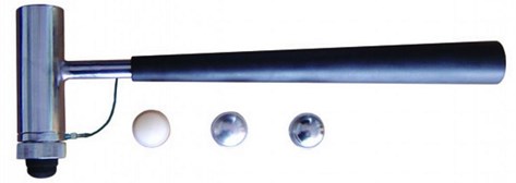
Table 1Comparisons between experimental modal and finite element modal
Order | Experiment / Hz | Simulation / Hz | Relative error / % |
R1 | 591.2 Hz | 597.8 Hz | 1.1 |
R2 | 1743.5 Hz | 1733.2 Hz | –0.6 |
R3 | 2742.3 Hz | 2715.1 Hz | –1.0 |
R4 | 3442.3 Hz | 3461.4 Hz | 0.6 |
N1 | 1961.2 Hz | 1976.5 Hz | 0.8 |
N2 | 2321.4 Hz | 2313.9 Hz | –0.3 |
N2 | 2921.3 Hz | 2932.5 Hz | 0.4 |
N3 | 3526.5 Hz | 3512.9 Hz | –0.4 |
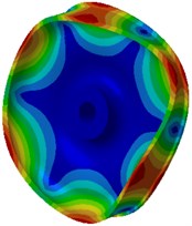
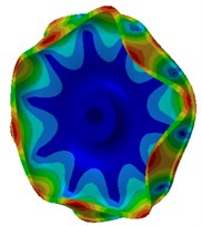
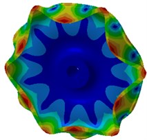
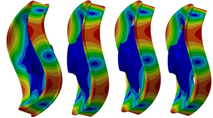
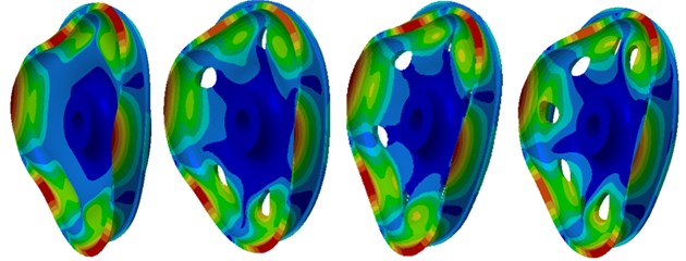
The mode of the finite element result was extracted as shown in Fig. 3. Fig. 3(a), (b), (c) and (d) were the radial vibration modals of wheels. From these figures, it could be seen that wheel tread carried on flexural vibration along the radius while wheel tread did not present any vibration mode in normal direction. The flexural vibration of wheel tread would result in noise radiation in the vehicle. Fig. 3(e), (f), (g) and (h) were normal vibration modals of wheels, from which it could be noticed that wheel web plate vibrated in normal direction while tread vibration was not presented in radial direction. The normal vibration of web plate would lead to the external noise transmission of wheels and influence the surrounding environment.
Fig. 3Radial and normal vibration mode of wheels
a) 597.8 Hz
b) 1733.2 Hz
c) 2715.1 Hz
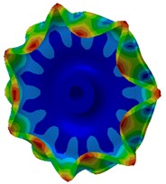
d) 3461.4 Hz
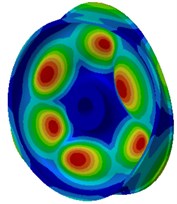
e) 1976.5 Hz
f) 2313.9 Hz
g) 2932.5 Hz
h) 3512.9 Hz
3. Acoustic boundary element model
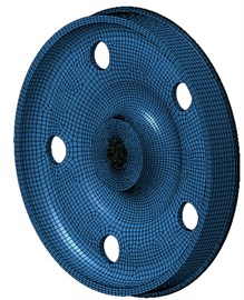
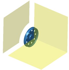
To prevent the acoustic leak caused by hub holes, additional elements were adopted to close hub holes. According to the geometric model in Fig. 1, the surface was adopted to obtain the boundary element. As a result, boundary element model was shown in Fig. 4(a). Boundary element meshing was also one of key factors affecting analytical precision. To ensure the accurate computation, there should be 6 elements in the minimum analytical wavelength. Namely, the maximum element length should be 1/6 less than the minimum analytical wavelength [13]. One thing to note was that boundary element meshes should be basically the same in size. Too large or too small sizes were not allowed. Too fine local meshing could not raise calculation accuracy because the calculation accuracy of fluid model was controlled by multiple elements [14]. In calculation, air density was 1.21 kg/m3 and sound velocity in the air was 344 m/s. The frequency range of calculation was 20 Hz-5000 Hz and step length was 10 Hz.
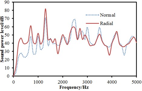
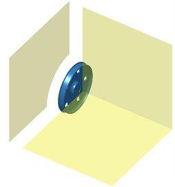
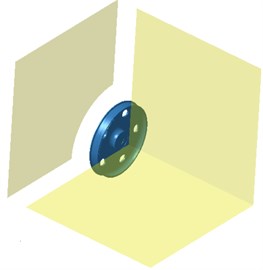
Plane field points in 3 directions were arranged around the wheel were as shown in Fig. 4(b) in order to observe the radiation noise and directivity of the wheel. Plane was parallel to the wheel plane. Plane and Plane were perpendicular to the wheel plane. The modal result computed by the above finite element model was imported into Virtual.Lab to couple with boundary element model. In this way, boundary element model could obtain the computational result of finite element and realize vibro-acoustic coupling. The boundary condition in the finite element model can be also mapped into the boundary element model. In addition, radial and normal loads could be respectively applied to the computational model to obtain the radiated sound power of radial and normal direction as shown in Fig. 5.
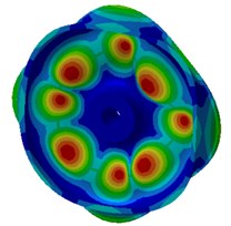
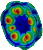
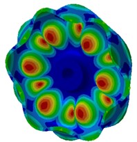
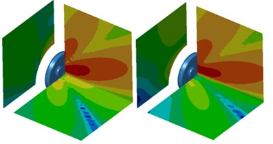
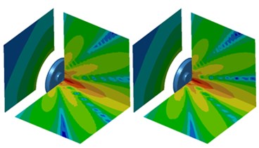
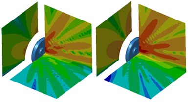
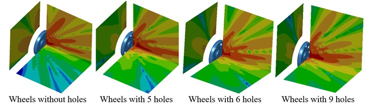
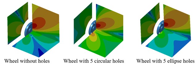
As displayed from Fig. 5, the sound power of radial radiation was significantly greater than that of normal radiation when the analyzed frequency was lower than 1000 Hz. The maximum sound power of radial radiation was 84.5 dB and corresponding frequency was 1421 Hz. The maximum sound power of normal radiation was 72.1 dB and corresponding frequency was also 1421 Hz. The sound power of normal radiation was greater than that of radial radiation when the analyzed frequency exceeded 2600 Hz. In the whole analyzed frequency band, the sound powers of radial and normal radiation showed obvious peak noises mainly because wheel had radial and normal modals. Under the action of corresponding exciting forces, modals would be excited to produce corresponding peak noises. The cloud pictures for the radiation noise of wheel under radial and normal excitations were extracted. The result was shown in Fig. 6. In the figure, the left cloud picture represented radial radiation noise and the right cloud picture stood for normal radiation noise for every analyzed frequency point. At the frequency of 700 Hz, the radiation noise of wheel was mainly spread along the and planes and showed obvious directivity. Radiation noise in the plane was relatively smaller. At the frequency of 1000 Hz, the radiation noise of wheel in the plane presented two obvious directions while the radiation noise of wheel in the and planes was not obvious. When the analyzed frequency was 1300 Hz, the radiation noise of wheel formed an obvious directivity noise at the boundary of and planes and the radiation noise of wheel in the plane became gradually significant. At the frequency of 2500 Hz, the radiation noise of wheel displayed obvious directivity in the and planes and was scattered in the plane. At the frequency of 3500 Hz, the wheel still demonstrated the most obvious directivity in the plane and showed three obvious directions in the plane. At the frequency of 4200 Hz, the radiation noise of wheel presented obvious directivity in three planes and showed many directions in various planes.
Fig. 4Boundary element model of radiation noise of wheels
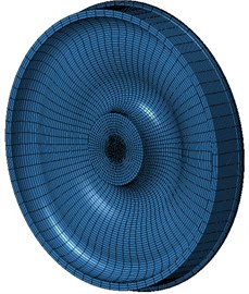
a) Boundary element mesh
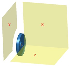
b) Field point mesh
Fig. 5Comparison between the radiated sound powers of wheel in radial and normal directions
4. Influence of web plate holes on the radiation noise of wheels
Opening holes on wheel web plate could effectively reduce the effective radiating area of web plate and thus decrease radiation noises. Therefore, it was necessary to adopt the method of numerical calculation to deeply study the radiation noise of wheel with holes.
Fig. 6Contours for the radiation noise of wheels under radial and normal loads
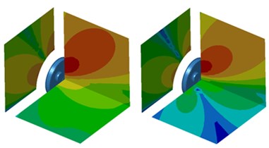
a) 700 Hz
b) 1000 Hz
c) 1300 Hz
d) 2500 Hz
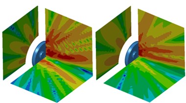
e) 3500 Hz
f) 4200 Hz
4.1. Influence of the hole number
Based on the geometric mode of web plate wheel without holes, the finite element model of web plate wheels with 5, 6 and 9 holes whose hole diameter was 20 mm and holes were located in the center of web plate and distributed uniformly to calculate its modal and compare with wheel without holes. The result was shown in Fig. 7. In the figure, differences in the vibration mode of various wheels could not be found and vibration modes basically kept the same. Therefore, it was necessary to further calculate radiation noise and observe the acoustic effects of various wheels.
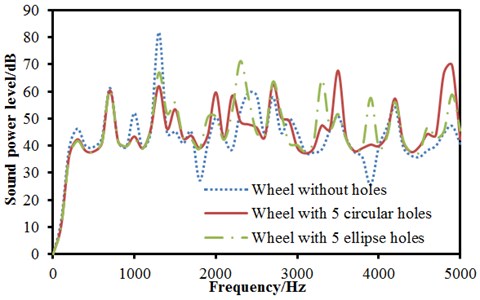
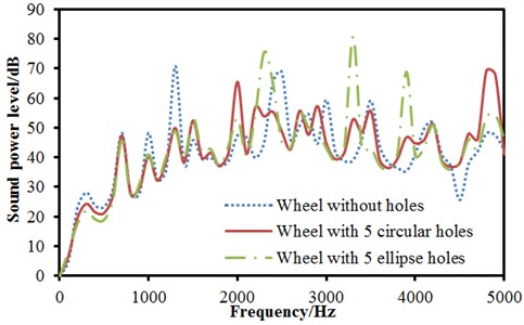
Boundary element models of various wheels were established based on the geometric model of wheels, as shown in Fig. 8, Fig. 9 and Fig. 10. The radiation noise of wheels under radial excitation was computed and compared with that of wheels without holes. The result was shown in Fig. 11(a). As displayed from Fig. 11(a), opening holes on wheel web plate really had certain influence on the radiation noise of wheels. When the analyzed frequency was lower than 1421 Hz, the radiation noises of several wheels basically showed the same change trend and size. At 1421 Hz, the maximum radiation noise of wheels without holes was 84.5 dB and the radiation noise of wheels with 5 holes had relatively minimum, namely 62.1 dB. With the further increase of the analyzed frequency, peak frequencies of radiation noises of various wheels were not consistent mainly because opening holes would have certain impact on the modal frequency of wheels. Under the action of excitation forces, modal peak noises would change to some degree. From the figure, obvious change rule could not be observed. The average radiated sound powers of various wheels were computed respectively. The average radiated sound powers of wheels without holes and with 5, 6 and 9 holes were 42.8 dB, 44.7 dB, 38.6 dB and 39.5 dB respectively. It indicated that the larger hole number of wheels did not mean better. When there were more holes, the rigidity of wheels would be certainly reduced. Under the action of the same exciting force, vibrations would be more obvious and radiation noises would be relatively larger. Fig. 11 (b) showed the comparison between the radiation noises of various wheels under normal excitation. When the analyzed frequency was lower than 1421 Hz, the result was similar to that under normal excitation. The average sound powers of various wheels were computed respectively. The average sound powers of wheels without holes and with 5, 6 and 9 holes were 40.6 dB, 38.7 dB, 39.2 dB and 39.8 dB respectively. Based on the above analysis, wheel with 6 holes had relatively minimum radiation noises under radial and normal excitations.
Fig. 7Comparison between the modals of wheel with holes
a) 700 Hz
b) 2500 Hz
Fig. 8Boundary element model of wheels with 5 holes
a) Boundary element mesh
b) Field point mesh
Fig. 9Boundary element model of wheels with 6 holes
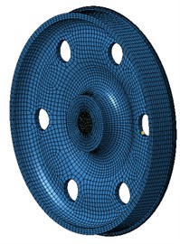
a) Boundary element mesh
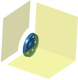
b) Field point mesh
Fig. 10Boundary element model of wheels with 9 holes
a) Boundary element mesh
b) Field point mesh
4.2. Influence of the hole shape
An in-depth analysis was conducted on the influence of the hole number of wheels on radiation noises above. In addition, the above holes were circular. Here, the shape of holes in wheels would be changed into ellipse and the number remained unchanged to establish the boundary element model of wheels as shown in Fig. 12. The radiation noise of wheels under radial excitation was computed and compared with that of wheels with circular holes and without holes. The result was shown in Fig. 13(a). It could be seen from Fig. 13(a) that changes in the radiation noise of three kinds of wheels were basically the same when the analyzed frequency was lower than 1421 Hz. At 1421 Hz, the radiation noise of wheels without holes was the maximum, followed by the radiation noise of wheels with ellipse holes. The radiation noise of wheels with circular holes had the minimum. It was mainly because opening holes in wheels effectively reduced the radiating area of wheel web plate and lowered radiation noise. When the analyzed frequency was more than 1421 Hz, changes in the radiation noise of three kinds of wheels presented no obvious regulations. The average sound pressure powers of three kinds of wheels were computed respectively. The average sound pressure powers of wheels without holes and with 5 holes and ellipse holes were 42.8 dB, 44.7 dB and 45.1 dB. It indicated that opening ellipse holes in wheels had less obvious effect than opening circular holes in wheels. Fig. 13(b) was the comparison between the radiation noise of wheels with ellipse holes under normal excitation and that of wheels with circular holes and without holes. Changes in the radiation noise of wheels when the analyzed frequency was lower than 1421 Hz were similar to those under radial excitation. The average radiation noises of various wheels were computed respectively. The average radiation noises of wheels without holes, with 5 holes and ellipse holes were 40.6 dB, 38.7 dB and 39.6 dB. According to the analyzed result, opening ellipse holes in wheels had less effect than opening circular holes in wheels.
Fig. 11Radiation noises of wheels with holes under radial and normal excitations
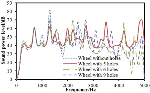
a) Radial
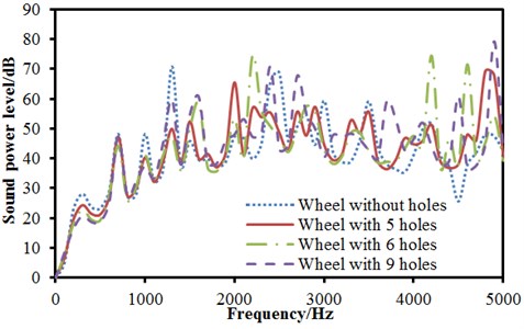
b) Normal
Fig. 12Boundary element model of wheels with ellipse holes
a) Boundary element mesh
b) Field point mesh
5. Acoustic radiation directivity
As displayed from Fig. 6, the radiation noise of wheels presented obvious directivity in , and planes. However, the distribution of directivity could not be quantitatively studied only through the contour of radiation noises. Therefore, it was necessary to compute the distribution curve for the directivity of acoustic radiation of wheels.
5.1. Influence of the hole number
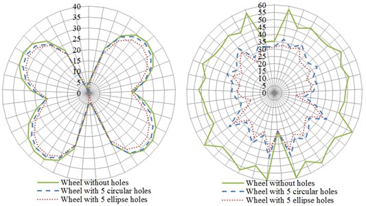
Fig. 14 showed curves for the influence of number of circular holes on the directivity of radiation noises of wheels. The left was distribution curves for the directivity of radiation noises under the action of normal excitation force and the right was distribution curves for the directivity of radiation noises under the action of radial excitation force. From the comparison curve on the left of Fig. 14(a), it could be found that radiation noises had maximum along the angle of 45° in the plane and presented a symmetrical structure when wheels were under the action of normal excitation force. The radiation noise of wheels without holes had relatively maximum while the radiation noise of wheels with 6 holes had relatively minimum. It was mainly because the modal of wheel web plate was excited under the action of normal excitation force and occupied a leading position. Therefore, radiation noises mainly came from the vibration of web plate. From the comparison curve on the right of Fig. 14(a), it could be noticed that the radiation noise of wheels without holes was obviously greater than that of other structures when wheels were under the action of radial exciting force. The radiation noise of wheels with 9 holes had minimum. In addition, the distribution curve was approximate to a circular curve. It was mainly because the flexural vibration of wheel tread occupied a leading position under the action of radial excitation force and the vibration of web plate was weakened. Fig. 14(b) was the distribution curve for the directivity of radiation noises of wheels in the plane. As displayed from the figure on the left of Fig. 14(b), the curve for the radiation noise of wheels with 5 holes was clearly different from that of other wheels under the action of normal excitation force. However, the distribution curves for the radiation noise of all wheels were similar under the action of radial excitation force.
Fig. 13Radiation noises of wheels with ellipse holes under radial and normal excitations
a) Radial
b) Normal
Fig. 14(c) presented the directivity distribution of radiation noise curve of wheels in the plane. As shown in the figure, the curves for the directivity of radiation noises of wheels were distributed completely symmetrically under the action of radial or normal excitation force and radiation noises had relatively maximum in the position of multiples of 30°. The radiation noise of wheels without holes had relatively minimum and the radiation noise of wheels with 9 holes had maximum under the action of normal excitation force. However, the radiation noise of wheels without holes was obviously greater than that of other structures under the action of radial excitation force.
Fig. 14The influence of number of circular holes on the directivity of radiation noises
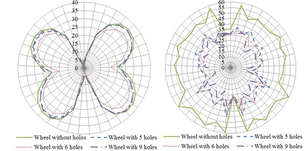
a) plane
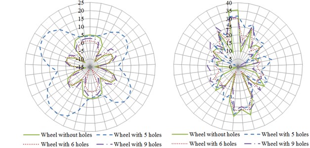
b) plane
c) plane
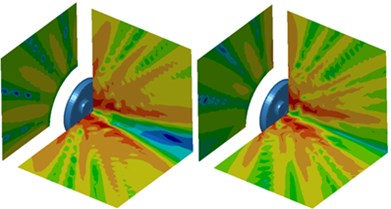
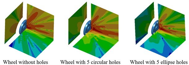
Contours for the directivity of radiation noises of wheels in each plane were extracted as shown in Fig. 15. As displayed from Fig. 15(a), contours for the radiation noise of wheels with 5 holes in the plane were totally different from that of other structures at the frequency of 700 Hz, which was reflected in the distribution curve of directivity as shown in Fig. 14(b). At 2500 Hz, contours for the radiation noise of wheel with 5 holes in the plane were slightly different from that of other structures. As displayed from the comparison between Fig. 15(a) and Fig. 15(b), the directivity distribution of radiation noises in the plane would be more obvious with the increase of the analyzed frequency.
Fig. 15Contours for the directivity of radiation noises of wheels with different circular holes
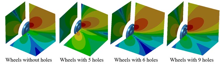
a) 700 Hz
b) 2500 Hz
5.2. Influence of the hole shape
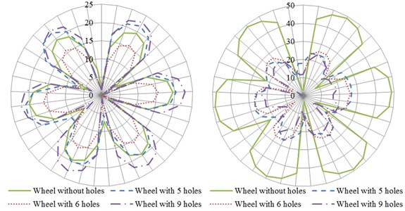
Fig. 16 presented distribution curves for the directivity of radiation noises of wheels with different hole shapes in various planes. The left was distribution curves for directivity under the action of normal excitation force, and the right was distribution curves for directivity under the action of radial excitation force. In the plane, distribution curves for the directivity of radiation noises of three kinds of wheels were similar and basically symmetric under the action of normal excitation force. However, distribution curves for the directivity of radiation noises of three kinds of wheels presented great differences under the action of radial excitation force and the directivity noise of wheels without holes was obviously greater than that of other two structures. As displayed from Fig. 16(b), shapes of distribution curves for the directivity of radiation noises of wheels with ellipse holes and circular holes were different in the plane. In the plane, curves for the directivity of radiation noises of three kinds of wheels were similar under the action of normal excitation force. However, curves for the directivity of radiation noises of three kinds of wheels were different to some extent under the action of radial excitation force in the plane and the directivity noise of wheels without holes was obviously greater than that of other two kinds of wheels. Additionally, values of directivity noises of wheels with ellipse holes and circular holes presented small differences.
Contours for the directivity distribution of radiation noises of wheels at 700 Hz and 2500 Hz were extracted as shown in Fig. 17. As displayed from Fig. 17(a), contours for the directivity of wheels with 5 holes in the plane were different from that of other two structures, which was also reflected in Fig. 16(b). At 2500 Hz, the directivity noise of wheels with ellipse holes in the plane was obviously less than that of other two structures.
Fig. 16The influence of the hole shape on the directivity of radiation noise of wheels
a) plane
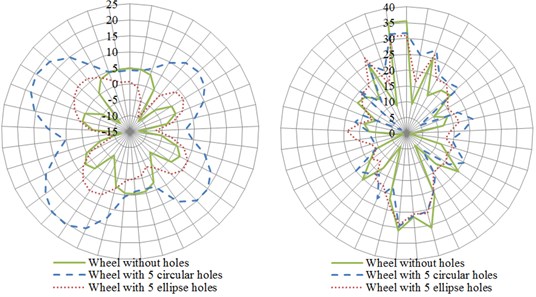
b) plane
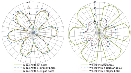
c) plane
6. Conclusions
1) The finite element model of wheels without holes was established to compute free modals and compare with the experimental result. The relative error was controlled within 5 %, which satisfied engineering requirements and indicated that the finite element model in this paper was reliable.
Fig. 17Contours for the directivity of radiation noises of wheels with different hole shapes
a) 700 Hz
b) 2500 Hz
2) Based on the finite element model and geometric model, the acoustic boundary element model of wheels was established. The radiation noise of wheels was computed under the action of radial and normal excitation forces. Results showed that the change trend and value of radiation noises of wheels were similar under the action of two kinds of excitations when the analyzed frequency was lower than 1421 Hz. However, the radiation noises of wheels under the action of two kinds of excitations were obviously different with the increase of the analyzed frequency. In addition, the radiation noise of wheels presented obvious directivity in three planes.
3) Boundary element models of wheels with 5, 6, 9 holes and ellipse holes were established to compute radiation noises and compare with wheels without holes. Results indicated that the radiation noise of wheels with 6 holes had relatively minimum under the action of radial and normal excitations. Radiation noises did not decrease with the increase of the hole number. Compared with the radiation noise of wheels with ellipse holes, the radiation noise of wheels with circular holes had some improvement.
4) Distribution curves for the directivity of radiation noises of various wheels were computed. According to the computational results, curves for the directivity of radiation noises were symmetric in the plane and radiation noises had relatively maximum in the position of multiples of 30°. Curves for the directivity of radiation noises of wheels with 5 holes were obviously different from that of other structures.
References
-
Thompson D. J. A review of the modeling of wheel/rail noise generation. Journal of Sound and Vibration, Vol. 231, Issue 3, 2000, p. 519-536.
-
Kitagawa T. The influence of wheel and track parameters on rolling noise. QR of RTRI, Vol. 50, 2009, p. 32-38.
-
Thompson D. J. Prediction of acoustic radiation from vibration wheels and rails. Journal of Sound and Vibration, Vol. 120, 1988, p. 275-280.
-
Thompson D. J., Jones C. J. C. Sound radiation from a vibrating railway wheel. Journal of Sound and Vibration, Vol. 253, 2002, p. 401-419.
-
Hslzl J. The noise optimization of high-speed railway wheels. Foreign Diesel Locomotive, Vol. 306, Issue 12, 1995, p. 27-29.
-
Sato K., Sasakura M. Acoustic characteristics of wheels with different web shapes. QR of RTRI, Vol. 47, 2006, p. 28-33.
-
Sasakura M., Sato K. Analytical study on vibration and acoustic characteristics of railway wheels with different shapes. QR of RTRI, Vol. 22, Issue 5, 2008, p. 17-22.
-
Efthimeros G. A., Photeinos D. I., Diamantis Z. G. Vibration/noise optimization of a FEM railway wheel mode. Engineering Computations, Vol. 19, Issue 8, 2002, p. 922-931.
-
Nielsen J. C. O., Fredo C. R. Multi-disciplinary optimization of railway wheels. Journal of Sound and Vibration, Vol. 293, 2006, p. 510-521.
-
Liu L. Y., Lei X. Y., Lian S. L. Influence of wheel parameters on wheel/rail noise. Journal of Noise and Vibration Control, Vol. 5, 2007, p. 74-77.
-
Fang R. Study on Vibration and Acoustic Radiation Characteristics of Wheel/Rail System. Southwest Jiaotong University, Chengdu, 2008.
-
Daneryd A., Nielsen J., Lundberg E. On vibro-acoustic and mechanical properties of perforated railway wheel. Proceeding of the 6th International Workshop on Railway and Tracked Transit System Noise, 1998, p. 305-317.
-
Benello P., Brennan M. J., Elliott S. J. Vibration control using an adaptive tuned vibration absorber with a variable curvature stiffness element. Smart Materials and Structures, Vol. 14, Issue 5, 2005, p. 1055-1065.
-
Deng H. K., Gong X. L., Wang L. H. Development of an adaptive tuned vibration absorber with magnetorheological elastomer. Smart Materials and Structures, Vol. 15, Issue 5, 2006, p. 111-116.
About this article

The manuscript was written and revised by Xunqian Tong, and it was translated by Jun Lin. Guanyu Zhang has proposed the opinion of this manuscript and the experiment was completed by Xi Zhu.
