Abstract
We applied multi-objective topology optimization to reduce vibration of the primary supporting structure of video satellites in the frequency domain. The optimal structure is obtained by the multi-objective topology optimization with stiffness and random vibration response as the targets. This is compared with the optimal structure obtained by single-objective topology optimization with stiffness as the target. The dynamic analysis results show that the root mean square values in all three spatial directions of the optimal structure by the multi-objective optimization are smaller than that of the single-objective optimization. The maximal declining value reaches 2.94 g, and the maximal declining degree is 30.6 %. The maximal declining response value on the top of the cylinder reaches 3.87 g with a degree of 33.0 %. The results demonstrate that the multi-objective optimization method significantly improves the vibration response of the base plate, which therefore suppressed the vibration of the satellite. An acceptance condition experiment is performed for the satellite with the optimal base plate from the multi-objective optimization. The dynamic analysis results match well with the experimental data, and verify the applicability of the multi-objective optimization.
1. Introduction
Random vibrating excitation, such as the impulse force and jet noise [1] produced during a rocket launching process, is directly transferred through the rocket-satellite adapter to the primary supporting structure of the satellite affecting the secondary structures, and also the performance and reliability of the satellite [2]. Therefore, it is necessary to optimize the structure of the satellite base plate to meet the stiffness requirement, while maintaining a high vibration reduction quality [3]. Micro-satellites [4, 5] are small-size and lightweight. A lightening design of the structure is necessary to maximize the load ratio. However, rare related researches have considered stiffness, vibration reduction, and low weight at the same time in a micro-satellite structure design. In this paper, we propose a multi-objective approach to maintain the balance of stiffness, vibration reduction, and low weight.
Up to the present, the topology optimization of satellite structures is mainly focused on the single-objective topology optimization (SOTO) [2, 4, 6], which ignores the random vibration of the satellite structure in its launch period and means that the dynamic characteristics of the structure cannot be optimized [6, 7].
The Jilin-1 smart video satellite is a video imaging micro-satellite weighing no more than 95 kg. The primary supporting structure of Jilin-1 is composed of the docking ring, base plate, and central cylinder. The base plate is located between the docking ring and the central cylinder. The mechanical environment of the rocket influences the base plate through the docking ring, and vibrations are transferred to the central cylinder. Consequently, the vibration characteristics of the base plate determine the mechanical properties of the satellite [8-10]. At present, most of topology design researches focused on SOTO [11-13]. The rests, which are multi-objective topology optimization (MOTO) [14-17], only focused on multi-stiffness, and rare MOTO researches are aimed at multi-dynamical responses. Wei. L et al. [5] optimized the primary load-bearing structure of earth observation micro-satellite by the SOTO method. Shao X. Y. et al. [6] researched the multi-stiffness optimization design based on MOTO. Different from these researches, we develop a multi-objective topology optimization model for the base plate which focuses on multi-dynamical responses. The MOTO model takes mass (volume fraction) as the optimum condition, the stiffness and the random response acceleration root mean square (RMS) value as the optimization objectives. A SOTO model with stiffness as the objective is also developed for the comparison with the MOTO model. By using the Optistruct, we performed iterative optimization using both models. The finite element analysis results show that the random response RMS value of the MOTO model is smaller than that of the SOTO model. The MOTO model significantly improves the vibration properties of the structure. An acceptance condition experiment is performed for the satellite with an optimal base plate designed using the MOTO. The finite element analysis results match well with the experimental data. Significant improvement is found in stiffness of the base plate and the reduction of vibration of the satellite. The design method successfully solves the problems in a smart satellite structure design and provides a new approach for the design of micro-satellite primary supporting structures.
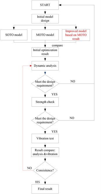
Fig. 1Flow chart of optimization design method
2. Topology optimization of satellite base plate
The SOTO and MOTO are taken on the initial model respectively at beginning. Then the 3d geometric model and the finite element model are built referenced on the better topology result. Considering the tough mechanical environment during the launch, the dynamic analysis and strength check both should be taken on the satellite base plate. Finally, the vibration test is conducted to verify the optimization design. The whole optimization method is shown in Fig. 1.
2.1. Establishment of finite element model of satellite base plate
As shown in Fig. 2, it is consist of 21029 nodes, 15183 body element in the FEM of the satellite base plate. 24 points of the central ring are used as the constraint boundary condition, and a lumped mass is used to simulate the optical camera load. The lumped mass is connected to the base plate by multi-point constraints. It makes use of 2A12 aluminum alloy, and the dynamic parameters [18] are shown in Table 1.
Fig. 2Finite element model of satellite base plate
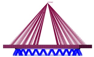
a) Front view
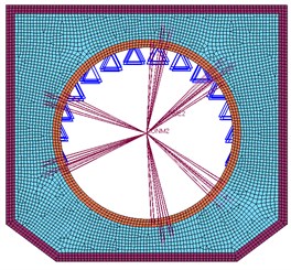
b) Vertical view
Table 1Dynamic parameters of 2A12 aluminum alloy
Elastic modulus () kg/mm2 | Poisson’s ratio () | Density (kg/mm3) |
70000 | 0.33 | 2.7 |
2.2. Single-objective topology optimization
In operation, the maximization of stiffness is usually equivalent to the minimization of compliance; the compliance is defined by the strain energy. Therefore, the topology optimized mathematical model [16, 17], based on the solid isotropic material with penalization method for conditions of given loading and a single-stationary boundary, can be expressed using the formulation detailed below. It is constrained by the volume of the overall structure and makes minimizing compliance its objective:
where is the compliance function, represents the material volume after optimization, is the design variable, and stands for the minimum value of the variable.
According to the mathematical model and practical requirements of the satellite, we optimize the design area on the basis of the stiffness topology optimization model, with compliance minimization set as its objective and volume fraction as its restriction. The result after iterative optimization is shown in Fig. 3.
The results show that to obtain a low weight, the optimized area turns into reinforced ribs. In addition, they take a central-divergent distribution, centering on the circle and distributed from the position of each camera to the border. According to the previous experience, central-divergent reinforced ribs can maximize the stiffness of the whole structure whilst maintaining a low weight. Hence, it is reasonable to take the result into consideration when designing for a low weight.
Fig. 3Result of single-objective optimization
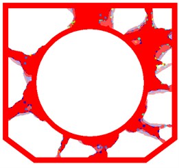
Fig. 4Result of multi-objective optimization
2.3. Multi-objective topology optimization concerning stiffness and random response
By using the compromise programming approach, considering stiffness and random response, the multi-factorial MOTO function in the frequency domain restricted by volume can be generated as below [15, 17]:
where, is the total number of the loading case, is the total number of the secondary loads, is the weight of the th load, and is the penalty factor (2); is the compliance function of the th load, with two polar values respectively; () is the random response function of the th load, with two polar values respectively.
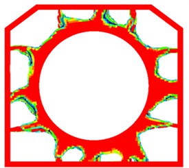
The boundary, restriction, and design area conditions are retaining as the same above. By iterative optimization, the following result is obtained, shown in Fig. 4.
To obtain a low weight, the optimized area turns into reinforced ribs. The distribution of the ribs is different to that shown in Fig. 4, and tends to be perpendicular to the border. Considering that the MOTO model adds a random response parameter, we make the assumption that the reinforced ribs that are perpendicular to the border help to reduce the RMS value of the random vibration response. To verify this assumption, a dynamic analysis was necessary to compare the two optimized results described above.
3. Modeling and mechanical analysis of optimized result
3.1. Construction of 3D model of base plate
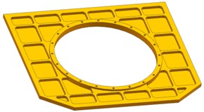
In light of the results presented above, the symmetry of the satellite, and the requirements of the manufacturing technique, we present two designs of the base plate. For plan A, based on the SOTO result, the base plate is designed with divergent reinforced ribs as shown in Fig. 5. For plan B, based on the MOTO result, the base plate is designed with divergent reinforced ribs that are perpendicular to the border as shown in Fig. 6. However, there is not only the optical camera installing on the base plate, but also one Fiber Optic Gyroscope and two Star Trackers beside the camera, and one TT&C Antenna, two GPS Antenna installing in the reverse side beside the docking ring. So, for plan C, based on plan B and to meet the requirement of installing place and structural interfaces, improved design is worked out, as shown in Fig. 7. During the design process, the size of the plate, border, central circle, and reinforced ribs maintained the same volume to minimize the mass difference of three models to less than 5 %.
To simulate the dynamic conditions, and to reflect the dynamic characteristics of the base plate of the satellite, it is not only necessary to investigate the random response characteristics of the base plate but also significant to take into consideration the random response characteristics on the top of the cylinder where the antenna is located.
Fig. 5Base plate models of central-divergent distribution reinforced ribs (Plan A)
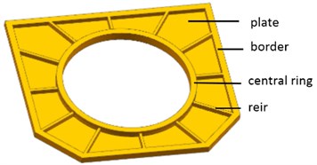
Fig. 6Base plate models showing distribution of reinforcing ribs (Plan B)
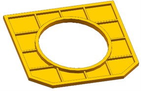
Fig. 7Improved design based on Plan B (Plan C)
3.2. Satellite FEM building
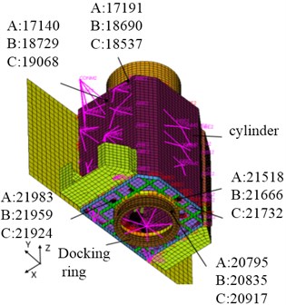
Based on the three models above, the FEM is built respectively. For plan A, the satellite FEM contains 34164 nodes, 24398 elements, 494 RBE2, 47 CONM2. For plan B, the satellite FEM contains 34114 nodes, 24362 elements, 494 RBE2, 47 CONM2. For plan C, the satellite FEM contains 34386 nodes, 24516 elements, 494 RBE2, 47 CONM2. During the vibration test, the satellite is fixed with the vibration table through the mounting surface of the docking ring. Therefore, in the finite element analysis, a node is set at the center of the docking ring. And then, the node and mounting surface of the docking ring are connected with the free degree of seven pressing points with the RBE2. During the analysis on the three plans, five sample nodes for vibration data collection are setting on the docking ring, base plate and cylinder, the specific locations are shown as in Fig. 8.
3.3. Comparative analysis of dynamic characteristics of above models
The dynamic analysis of the supporting base plate consists of modal analysis [18], and random response analysis. The modal analysis focuses on the frequencies of the main formations, including the reciprocating frequency and torsional frequency of the first-order movement in the , , and directions. The random response analysis concentrates on the comparison of the RMS value of the random response vibration for the three plans [19, 20]. Besides the comparison among the plans, we also compare the optimized model with initial model in which the base plate is a stock structure without lightweight design.
Fig. 8Sample nodes in FEM of satellite
3.3.1. Modal analysis
We identified the structure parameter of the base plate based on the original and optimized design of the satellite, then applied these parameters to the satellite model. The model analysis result is presented in Table 2.
By comparing the first-order frequency in three plans in Table 2, the conclusions are drawn as follows:
Firstly, among three plans, plan A sees the largest stiffness with first-order frequency 32.08 Hz. However, compared with the initial model, plan A’s first-order frequency declines 5.24 Hz with 16.33 % by declining rate. Therefore, topology optimization reduces satellite’s stiffness in a certain range.
Secondly, the first-order frequency in plan B is 1.66 Hz lower than plan A; the declining rate is 5.2 %. The contributive efficiency of the stiffness of the central-divergent reinforced ribs overcomes the border-vertical reinforced ribs.
Thirdly, comparing with first-order frequency in plan B, it is 0.21 Hz higher in plan C, and the raising rate is 0.7 %. Conclusion can be obtained that the first-order frequency in plan B and plan C are almost the same.
Finally, according to lunch vehicle requirements, the first-order reciprocating frequency must be above 20 Hz and avoid 40±3 Hz; therefore, all the plans meet this requirement.
Table 2Modal analysis results
Initial model | Plan A: base plate | Plan B: base plate | Plan C: base plate | Initial model /Plan A | Plan A/Plan B Variation range | Plan C/Plan B Variation range | |
First-order mode (Hz) | 37.32 | 32.08 | 30.42 | 30.63 | 0.1633 | 0.052 | 0.007 |
3.3.2. Random response analysis
Smart video satellites adopt a carry-on launching model, and they are located at the margin of the supporting cabin in fairing of launch vehicle. During the launching process, the satellite encounters severe dynamic conditions. The excitation for random vibration are shown in Table 3 and Fig. 9.
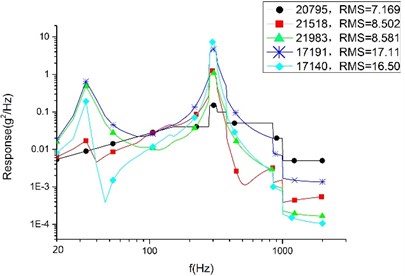
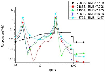
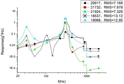
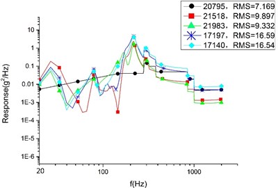
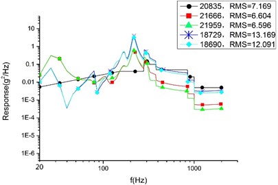
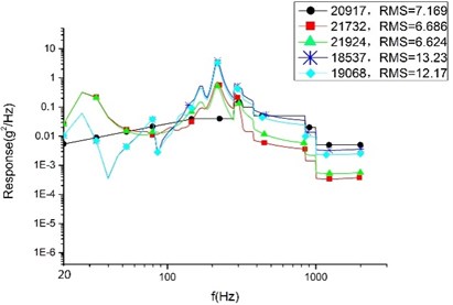
By using Patran/Nastran [19], twelve cases are studied, which consist of a random response analysis of the , , and directions of plan A, plan B and plan C and the initial model. Two sample points from the base plates and two sample points from the cylinder top are selected to generalize the analytic result. An excitatory input point is also selected for contrast. The analytic results for each direction are presented as in Figs. 10, 11, and 12.
Table 3The data of random vibration excitation of smart video satellite
Frequency range (Hz) | Acceptance conditions | ||
Power Spectrum Density ( / Hz) | Total RMS of acceleration (g) | ||
Value | 20-150 | +3 dB/oct | 7.17 |
150-280 | 0.04 | ||
280-320 | 0.15 | ||
320-380 | 0.1 | ||
380-850 | 0.05 | ||
850-1000 | 0.02 | ||
1000-2000 | 0.005 | ||
Direction | , , | ||
Time | 1 min for each direction | ||
Fig. 9Curve of random vibration excitation of smart video satellite
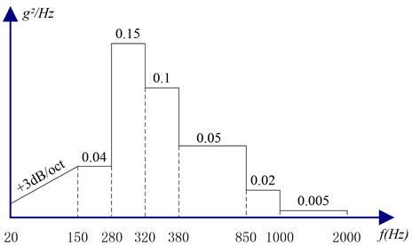
Fig. 10RMS value of random vibration response analysis in X direction
a) Plan A
b) Plan B
c) Plan C
Fig. 11RMS value of random vibration response on base plate sample points in Y direction
a) Plan A
b) Plan B
c) Plan C
Fig. 12RMS value of random vibration response on base plate sample points in Z direction
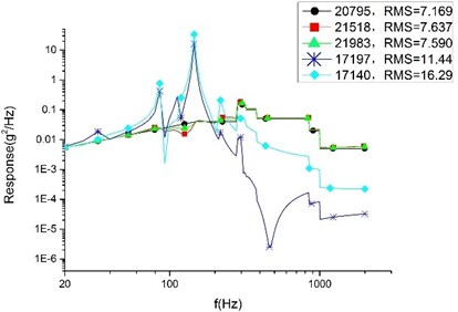
a) Plan A
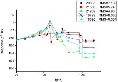
b) Plan B
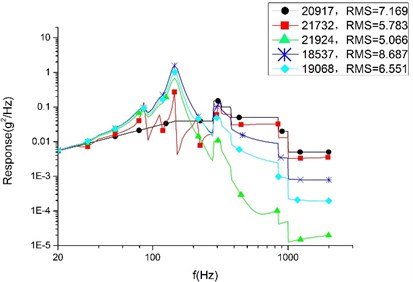
c) Plan C
In the finite element analysis, different nodes can take different response values, even on neighboring nodes. To make a rational quantification, we adopt a mean value (accurate to the second decimal place) to compare the result. According to Table 4, the average response value of each analysis and the SAD value and variation range between each plans are presented. By considering the comparing results, the conclusions are drawn as follows:
Firstly, among the optimized three plans, plan A sees the largest response in three directions. However, compared with the initial model, the cylinder in direction of plan A sees the largest declining response value with 7.07 g and the largest declining rate with 38.34 %. We can draw a conclusion that the SOTO plan and MOTO plan are both effective in reducing vibration to a great extent.
Secondly, it shows that compared with plan A, the random response value of the base plate and cylinder decline noticeably in Plan B, and that the direction see the largest declining rate. The base plate’s random response value declines by 31.78 % and the value of the cylinder declines by 23.36 %. The declining values are 3.15 g and 3.87 g, respectively. 33.16 % is the largest declining rate for the satellite, representing the random response of the cylinder in the Z direction. Therefore, it can see that plan B is superior to plan A in reducing vibration. That is to say, MOTO is more conducive to vibration reduction.
Finally, compared with plan B, the random response value of the base plate and cylinder raised slightly in plan C. The direction see the largest raising rate in cylinder which increase value is 0.23 g and variation range is 1.2 %. The largest variation range is 2.17 % representing the base plate of direction and the raising value is 0.14 g. These comparing results show that plan C is larger than plan A in vibration value, but the variation range is so little enough that there is rarely difference for the satellite’s devices in mechanical environment between plan B and plan C. So, we can conclusion that plan C remain the optimum mechanical property of plan B.
Taking results into consideration, plan C can both meet the stiffness requirement and optimizes the vibration of the structure and satellite. Therefore, it is adopted in the design of the base plate of the video satellite.
Table 4Random response results
Base plate | Cylinder | |||||
Direction | ||||||
Initial model | 13.05 | 12.63 | 11.97 | 21.37 | 19.86 | 18.44 |
Plan A | 8.54 | 9.61 | 7.61 | 16.81 | 16.57 | 11.37 |
Plan B | 7.53 | 6.6 | 5.36 | 12.85 | 12.63 | 7.51 |
Plan C | 7.6 | 6.66 | 5.43 | 13 | 12.7 | 7.62 |
Initial Model/Plan A | 4.51 | 3.02 | 4.36 | 4.56 | 3.29 | 7.07 |
SAD value | ||||||
Initial Model/Plan A | 0.3456 | 0.2391 | 0.3642 | 0.2134 | 0.1657 | 0.3834 |
Variation range | ||||||
Plan A/Plan B | 1.01 | 3.15 | 2.25 | 3.96 | 3.87 | 3.77 |
SAD value | ||||||
Plan A / Plan B | 0.1183 | 0.3178 | 0.2957 | 0.2356 | 0.2336 | 0.3316 |
Variation range | ||||||
Plan B/ Plan C | 0.07 | 0.06 | 0.07 | 0.15 | 0.07 | 0.11 |
SAD value | ||||||
Plan B/ Plan C | 0.0093 | 0.0091 | 0.0131 | 0.012 | 0.0055 | 0.0146 |
Variation range | ||||||
3.4. Strength checking
3.4.1. Calculation conditions
According to the mechanical conditions of the vehicle, and considering certain safety factors, the design load of the following conditions are analyzed: 12 g to the direction overload, 3 g to the and direction overload.
3.4.2. Analysis of satellite overload
Overload analysis in 3 directions of the satellite is carried out with the conditions listed above. The Stress contour is shown in Fig. 13.
Analysis results show that 34.9 MPa with the maximum stress, 40.1 MPa with the maximum stress and 69.8 MPa with the maximum stress. The maximum stresses of the 3 directions are all happened to elements of the base plate where fixed with the docking ring.
The material of the base plate and docking ring is aluminum alloy which failure stress is 420 MPa. The structural safety margin is calculated taking into account the safety coefficient 1.8, shown in Table 5.
Table 5Calculation of structural safety margin
Operating stress (MPa) | Safety coefficient | Design load (MPa) | Failure stress (MPa) | Safety margin |
69.8 | 1.8 | 125.64 | 420 | 2.34 |
Fig. 13Analysis of the satellite overload
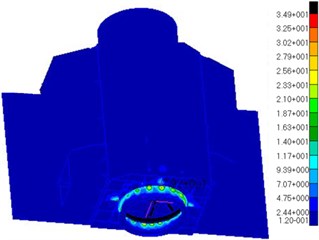
a) Stress contour of direction
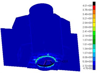
b) Stress contour of direction
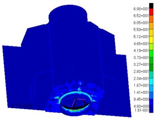
c) Stress contour of direction
Based on the static and dynamic analysis above, two following conclusions will be gotten:
Fist, dynamic analysis shows that Plan C is able both to meet the requirements of stiffness, and has a great effect on the vibration damping of the satellite structure.
Second, static analysis shows that Plan C can satisfy the requirement of the satellite structure strength. According to the above two conclusions, Plan C is chosen for use in the design of the satellite’s base plate. The test structural sample is manufactured based on Plan C, shown as Fig. 14.
4. Experimental verification
The vibration experiment using the whole satellite is performed at a 9 t water-cooled vibration table at the Changchun Institute of Optics Fine Mechanics and Physics, as shown in Fig. 15. The vibration response data of the base plate is collected by acceleration transducers located on the base plate and cylinder top. The random vibration response results are shown in Fig. 16 and 17. Tables 7 and 8 provide comparisons of the results from the experiment and finite element analysis [21, 22].
Fig. 14Test structural sample is manufactured based on Plan C
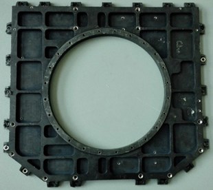
Fig. 15Vibration experiment of smart video satellite
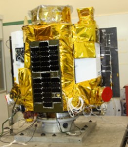
Fig. 16RMS value of random vibration response of smart video satellite base plate
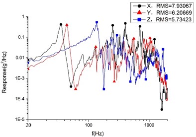
Fig. 17RMS value of random vibration response of smart video satellite cylinder
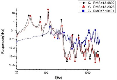
Table 6Comparison of first-order model of base plate in three directions between finite element analysis and vibration experiment
First-order model (Hz) | |
Finite element analysis | 30.42 |
Vibration experiment | 29.5 |
Analytical error value | 0.92 |
Relative analytical error | 0.031 |
Table 7Comparison of random response RMS value of base plate between finite element analysis and vibration experiment
Base plate | Cylinder | |||||
Direction | (g) | (g) | (g) | (g) | (g) | (g) |
Finite element analysis | 7.6 | 6.66 | 5.43 | 13 | 12.7 | 7.62 |
Vibration experiment | 7.93 | 6.21 | 5.73 | 13.49 | 13.29 | 7.1 |
Analytic error value | 0.33 | 0.45 | 0.32 | 0.49 | 0.59 | 0.52 |
Relative analytic error | 0.0416 | 0.0725 | 0.0524 | 0.0363 | 0.0444 | 0.0732 |
The static analytic error, 0.92 Hz, and the relative analytic error, 3.1 %, fall within reasonable bounds. The model analysis results match the practical results. In addition, the maximum error value of the finite element analysis of the random response is 0.59 g, and the maximum relative error is 7.32 %. Thus, the random analysis matches the real condition.
The comparison between the analytic results and vibration experiment results demonstrates the validity of the finite element model.
5. Conclusions
By applying MOTO, it succeeds in reducing vibration of the satellite canister structure. The conclusions are drawn as follows:
First, taking the base plate of satellite as its objective, the research verifies the superiority of MOTO in vibration reduction of the satellite canister structure. It provides a new way of designing the satellite canister structure.
Second, we design a vibration reduction plan for the supporting base plate of the satellite. The RMS value of the random response declines in three directions. The maximum declining value reaches 2.94 g, and the maximum declining degree is 30.6 %. The maximum declining response value on the cylinder top reaches 3.87 g with a degree of 33.0 %. The design greatly enhances the dynamic characteristics of the primary supporting structure, improves the dynamic condition of the satellite, and maintains the safety of every single structure. The video satellite designed using the MOTO approach has passed the dynamic condition examination and been launched successfully.
References
-
Johnson C. D. Protecting satellites from the dynamics of the launch environment. AIAA-2003-6266, 2003.
-
Johnson Conor D., Wilke Paul S. Protecting satellites from the dynamics of the launch environment. SPC & LPV Dynamics Environments Workshop, 2004.
-
Bronowicki A. J. Vibration isolator for large space telescope. AIAA Journal of Spacecraft and Rockets, 2005.
-
Kaj Lundadhl, von Scheele Fredrik Swedish small satellites. Technovation, Vol. 2, Issue 3, 2000, p. 287-297.
-
Wei L., Jin G., Xie X. G. Optimized design and test for primary load-bearing structure of earth observation micro-satellite. Optics and Precision Engineering, Vol. 23, Issue 11, 2015, p. 3183-3191.
-
Shao Xinyu, Chen Zhimin, Fu Mingang Multi-Objective Topology Optimization of Structures Using NN-OC Algorithms. Advances in Neural Networks. E-Publishing Inc., New York, 2007. p. 204-212.
-
Yang X. Y., Xie Y. M., Steven G. P. Evolutionary methods for topology optimization of continuous structures with design dependent loads. Computers and Structures, Vol. 83, 2005, p. 956-963.
-
Sarafin T. P., Larson W. J. Spacecraft Structures and Mechanisms: from Concept to Launch. Springer, 1995.
-
Wilson F. C. Recent advances in satellite propulsion and associated mission benefits. Recent Advances in Satellite Propulsion, Vol. 12, 2006, p. 14.
-
Johnson C. D. Protecting satellites from the dynamics of the launch environment. AIAA-2003-6266, 2003.
-
Ma Z. D., Kikuchi N., Cheng H. C. Topological design for vibrating structures. Computer Methods in Applied Mechanics and Engineering, Vol. 121, 1995, p. 259-280.
-
Bendsoe M. P., Sigmund O. Topology Optimization: Theory, Methods and Application. Springer, Berlin, 2003, p. 9-69.
-
Hassani B., Hinton E. Homogenization and Structural Topology Optimization Theory, Practice and Software. Springer, London, 1999.
-
Deaton Joshua D., Grandhi Ramana V. A survey of structural and multidisciplinary continuum topology optimization: post 2000. Structural and Multidisciplinary Optimization, Vol. 49, 2014, p. 1-38.
-
Min S., Nishiwaki S., Kikuchi N. Unified topology design of static and vibrating structure using multi-objective optimization. Computers and Structures, Vol. 75, 2000, p. 93-116.
-
Krog L. A., Olhoff N. Optimum topology and reinforcement design of disk and plate structures with multiple stiffness and eigen frequency objectives. Computers and Structures, Vol. 72, 1999, p. 535-563.
-
Fan W. J., Fan Z. J., Su R. Y. Research on multi-objective topology optimization on bus chassis frame. China Mechanical Engineering, Vol. 19, Issue 12, 2008, p. 1505-1508.
-
Lagaros N. K., Plevris V., Papadrakakis M. Multi-objective design optimization using cascade evolutionary computations. Computer Methods in Applied Mechanics and Engineering, Vol. 194, Issues 30-33, 2005, p. 3496-3515.
-
Thampi Vidyasagar S. K. S. N. Random Vibration Analysis of Space Flight Hardware Using NASTRAN. GE Government Services, USA.
-
Jaap W. Random Vibrations in Spacecraft Structures Design. Springer, USA, 2009, p. 162-163.
-
Boudjemai A., Amri R., Mankour A. Modal analysis and testing of hexagonal honeycombplates used for satellite structural design. Materials and Design, Vol. 35, Issue 1, 2012, p. 266-275.
-
Derwood C. I., Crawford M., Ward J. W. A low cost modular nanosatellite based on commercial technology. Proceedings of the 12th Annual AIAA/USU Conference on Small Satellite, SSC98-V-4, AIAA/USU, 1998.
Cited by
About this article

The authors would like to thank the financial support of the National Natural Science Foundation for Young Scholar of China (No. 61505203) and Youth Innovation Promotion Association CAS (No. 2011171).
