Abstract
This research intends to analyze and improve the flow-induced noise of an in-line fan with Helmholtz resonator by the numerical simulation. At first, the flow and acoustic fields associated with the fan are simulated and analyzed via the CFD simulation. Subsequently, a thorough understanding on the aerodynamic and acoustic features of this mixed-flow fan is achieved. Later, to reduce the fan noise, a set of Helmholtz resonators for this inline-fan is designed and installed onto the critical regions inside the fan. Also, the flow-induced-noise reduction due to the resonator is examined and discussed in details. As a result, the maximum noise reductions on the 1st and the 2nd characteristic frequencies are obtained at 6.9 dBA and 9.8 dBA, respectively. Moreover, there is a minor noise-elimination effect found on the other harmonic frequency while the significant result appears on the designed characteristic frequency. However, all resonators used yield a significant noise reduction at the second BFF. In conclusions, a comprehensive parametric study on Helmholtz resonator is carried out and summarized for attaining a design guideline for its application on the in-line fan. The accomplishment of this study provides a systematic scheme of noise reduction for an inline-fan with the addition of Helmholtz resonator design.
1. Introduction
While technology develops along with time, the computer efficiency and CFD computation also keep enhancing continuously. Nowadays, the prediction and evaluation of acoustic performance gradually becomes a realistic engineering tool. The annoying noise caused by the in-line fan is the major obstacle in promoting its utilization and becomes the task of this research. The main objective of this research intends to study the application of Helmholtz resonator on the noise control of an in-line fan. Currently, the researches and developments for noise control of inline fan are mostly focusing on reducing the blade passage frequency (BPF) noise, which is also called the narrow-band noise. This tonal frequency is the most annoying for human with regards to the comfortable decibel level. It is well known that the cut-off region is the main noise source, and the effect of noise control of this fundamental frequency is extremely important.
From previous literatures [1-3], Helmholtz and /4 resonators have a similar, obvious noise reduction effect on the narrow-band sound, but the appearance size for Helmholtz resonator can be adjusted subjecting to resonant cavity and neck size for a specific frequency of abnormal sound. For this reason, Helmholtz resonator has a better feasibility on the size consideration, it implements easily with different fan types and geometries due to a smaller volume needed. This resonator is not only used for suppressing a few narrow-band noises simultaneously, but also is appropriate for eliminating other board-band abnormal sound caused by fan rotation.
First of all, Alster [1] proposed a calculation mean for the resonant frequencies of resonators with a better accuracy, and it successfully eliminated the big calculation error encountered in the applications of previous formula. Thus, the parameter modification on the resonator can be evaluated systematically in the future application. Several articles [2-4] focused on analyzing the mathematical models and calculated the transmission loss induced by the Helmholtz resonator. Parente [5] investigated and achieved the purpose of noise reduction by automatically adjusting the appearance incorporated with a feedback system.
Afterwards, Han [6] performed the Helmholtz resonator noise reduction studies by proposing various resonators mounted in the pipeline. The corresponding measurement was carried out by utilizing the acoustic generator and the sound power level, and the results indicated that a very good sound suppressing effect on the characteristic frequency of the resonators. More recently, Han and Rhim [7] utilized this concept to the high-frequency noise research associated with the thin hard disk, the experimental results showed that the total sound pressure level (SPL) can be reduced by more than 1.5 dB when a compound resonator type is employed.
As stated above, resonator is a promising technology to eliminate BPF noise. In this research, the commercial CFD software Fluent [8] is chosen to execute the acoustic simulation. The flow and acoustic fields associated with the fan are calculated and analyzed via the CFD simulation. This work integrates design theory and CFD simulation to propose several resonators with different sets of design parameters, such as neck diameter, neck length, and length of a resonate chamber, to find out a better noise control on BPF noise. It is expected that the design and evaluation method established here can provide a design guideline for the Helmholtz resonator.
2. Model description
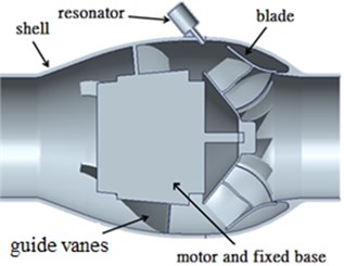
Fig. 1 shows that the original in-line fan consists of a housing, guiding blade, rotor blades, and motor with fixed base. The inline fan is equipped with a 93.4 mm-in-diameter impeller in the length of 266 mm, and running at the rotational speed of 3,300 rpm. The detailed sizes of the reference in-line fan are listed in Table 1.
Fig. 1Schematics of the original fan
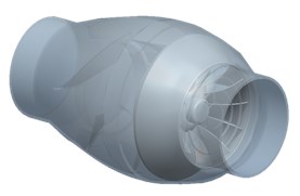
a) Perspective view
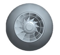
b) Front view
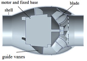
c) Side-sectional view
Table 1Sizes of the prototype in-line fan
Reference fan | |
Diameter of housing | 149.8 mm |
Rotating speed | 3,300 rpm |
Inlet diameters | 93.4 mm |
Impeller diameter | 141.8 mm |
Impeller height | 57.7 mm |
Blade number | 12 |
Housing length | 266 mm |
Table 2Resonators with different design parameters
Design-A1 | Design-A2 | |
Target frequency | 660 Hz | 1,320 Hz |
Neck diameter () | 3 mm | 4 mm |
Neck length () | 15 mm | 15 mm |
Chamber diameter | 14 mm | 14 mm |
Chamber length | 19 mm | 9 mm |
2.1. Design parameters of resonator
Due to the various geometries of Helmholtz resonators, there are some related limitations have to be set as design parameters. The chamber volume of resonator is set as hollow circular shape, and the dimension of resonator is shown in Fig. 2(a). Here, the principle idea of resonator design is to keep the neck length and the chamber diameter being fixed. Furthermore, it is needed to set fundamental frequency operating at 3,300 rpm. The complete parameters are included in Table 2.
Fig. 2Schematic diagrams for resonator and fan equipped with Helmholtz resonator
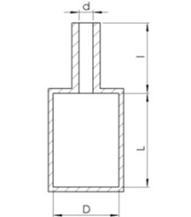
a) Resonator
b) Fan with Helmholtz resonator
2.2. Installing location and number of resonators
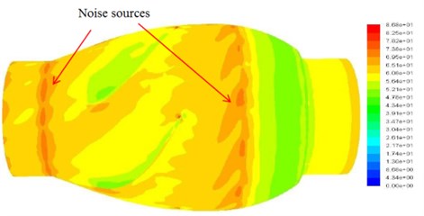
As illustrated in Fig. 2(b), the installing locations of resonators are selected at the blade exit, the fan inlet, the guiding vanes, and the fan discharge. The source of noise caused by fan is analyzed by means of numerical simulation as indicated in Fig. 3. Then, the Helmholtz resonators are placed on the outer housing (that is near the blade’s exit), and the corresponding acoustic simulation is executed. The effect of noise reduction is estimated by means of simulation, and the CFD verification is executed by comparing the corresponding test and simulation results.
Fig. 3Distribution of the sound pressure for the original in-line fan
In this study, the number of Helmholtz resonator applied onto fan are selected as 2, 5, and 10, and the simulation of flow filed and acoustic field are also executed, respectively. Note that this research focuses on the noise reduction of the 1st and the 2nd characteristic frequencies.
3. Numerical scheme
To simulate the induced flow inside the in-line fan, the commercial CFD software Fluent [8] is utilized to solve the fully three-dimensional, incompressible Navier-Stokes equations with the standard turbulence model, and the LES turbulence model is adopted to calculate the oscillation of velocity and temperature results. The ANSYS Fluent solves the Navier-Stokes equation by using an unstructured finite-volume method. The numerical calculation is executed with the moving reference frame (MRF) model to deal with the rotating fluid for an in-line fan. Regarding the acoustic analysis, this numerical simulation solves the unsteady flow field by means of the sliding mesh technique to capture the instantaneous pressure fluctuation and calculate it to the frequency domain. The LES turbulence model is adopted to calculate the sound effect of the small eddies enhanced pressure fluctuation.
Also, the modified SIMPLE method and Pressure-Implicit with Splitting of Operators (PISO) coupling method are implemented to speed up the efficiency of the pressure calculation for both steady and unsteady cases. The PISO algorithm adopts additional corrections to satisfy the momentum balance more closely, especially for the transient problems. The governing equations, turbulence model, acoustic model, and boundary conditions are summarized below.
The continuity and momentum equations in conservation form are expressed as:
Continuity equation:
where and are the velocity tensor and the source term, respectively.
Momentum equation:
where is the gravity, and is the body force.
When the fluid inertia affects the flow field more significantly than the fluid viscosity, the flow develops into a turbulent flow. Turbulent flows are characterized by fluctuating velocity fields, and cause many eddies due to this fluctuation. Incorporated with the -epsilon model, the Navier-Stokes equations can be solved using CFD method:
where Reynolds stresses are modeled employing the Boussines hypothesis [9]. And the turbulent viscosity is computed as a function of turbulence kinetic energy and dissipation rate:
where and are the turbulent kinetic energy generated by the mean velocity gradients and buoyancy. represents the contribution of the fluctuating dilatation in compressible turbulence to the overall dissipation rate, and , , , , and are model constants [10].
In addition to the - model, this study adopts the LES model [11, 12] to solve the large eddies in this unsteady flow field for the purpose of calculating sound pressure. The LES model solves large eddies directly by filtering the time-dependent Navier-Stokes equations, while small eddies are computed using the subgrid-scale Smagorinsky-Lilly model. A filtered variable is defined by:
where is the fluid domain, and is the filter function that determines the scale of the resolved eddies. Through finite-volume discretization, the filtering operation can be represented as:
where is the volume of a computational cell. The filter function determines the filter scale and executes the filter process:
Filtering the Navier-Stokes equation leads to:
where and are stress tensors due to molecular viscosity and the subgrid-scale stress.
In this work, several appropriate assumptions and boundary conditions are made to simulate the actual flow patterns of this in-line fan. They are described as follows:
3.1. Boundary conditions
The pressure at outlet surface is set to be one atmosphere. Also, the mass flow rate of each operating point at outlet boundary surface is set for calculating the corresponding static pressure. Regards wall boundary condition, this numerical model sets the no-slip boundary condition on the solid surfaces of the wall.
3.2. Moving reference frame (MRF)
The numerical investigation deals with the rotating flow in turbomachine via the MRF in the CFD codes. The rotating wall surfaces are treated as stationary boundaries relative to the rotating frame in this model. When the equations of motion are solved in this rotating reference frame, the acceleration of the fluid is supplemented by additional terms that appear in the momentum equations.
3.3. Sliding mesh boundary condition
The sliding mesh model is employed to compute the unsteady flow feature when a sound pressure solution for rotor-stator interaction is considered. This technique divides mesh domain into the rotating and the static zones. Each zone is bounded by interface boundary, and adjacent two meshes between rotor and stator move relative to each other along the grid interface.
4. Results and discussions
From CFD simulation result of the original inline fan, the peak of narrow-band noise is easily generated due to the extremely turbulent pressure fluctuations observed at the blade exit and the clearance between the rotor blade and housing (see Fig. 3). Therefore, the resonators are installed at these places, and the assembled direction is parallel to the incoming airflow to prevent the influence on the main flow direction. The assembled fan module is illustrated in Fig. 2(b). From which, the implement of resonators is located at some suitable places according to the flow field analysis of the original fan (see Fig. 3), and specified number (2, 5, and 10) of resonators are equally placed. Noticeably, these resonators are designed purposely to reduce the corresponding the 1st and the 2nd characteristic frequencies, and are denoted by A1 and A2 resonators, respectively. Thereafter, these resonator models are inputted to CFD solver for verifying their noise reduction effects.
Taking the acoustic pressure simulation of A2-5 fan design (-5 representing 5 resonators) as an example, Fig. 4 presents that the SPL comparison between the original fan and A2-5 design, which is aimed at reducing the 2nd harmonic frequency. As expected in the design goal, the decreasing tendency of acoustic pressure at the 2nd characteristic frequency is observed clearly.
Table 3 summarizes the CFD simulation outcomes for all resonators with different design parameters aiming at various characteristic frequencies. After observing the noise reduction effects, the decreasing phenomenon on acoustic pressure at harmonic frequencies is well demonstrated. For the A1 resonator aiming at the 1st characteristics, the first harmonic frequency is reduced by the amount of 2.0-6.9 dBA while the lowest decrease (2 dBA) is found at the 10-resonator case (A1-10). At the same time, a good reduction ranging from 2.4-4.1 dBA is observed at the second characteristic frequency. In the other end, a much better reduction ranging from 4.8 to 9.8 dBA is attained for the second resonator (A2) while the best reduction is identified at the case of 5 resonators (A1 resonator). Also, there is a slight noise reduction (0.9-2.2 dBA) is recorded on the first characteristic frequency. Consequently, a superior effect is attained for the second resonator over that of the first resonator while the best result is identified at the second resonator (A2-5) with the 9.8 reduction on the 2nd harmony.
Fig. 4The SPL comparison between the A2-5 fan and the original fan
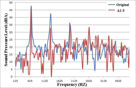
Table 3Acoustic-pressure simulation for the effects on the characteristic frequencies for the first design resonator and the second design resonator
The effect of the first resonator (A1) for various characteristic frequencies | |||||||
Base | A1-2 | Reduction | A1-5 | Reduction | A1-10 | Reduction | |
1st BPF | 47.7 | 45.5 | –2.2 | 40.7 | –6.9 | 45.6 | –2.0 |
2nd BPF | 42.5 | 40.1 | –2.4 | 38.3 | –4.1 | 39.2 | –3.2 |
The effect of the second resonator (A2) for various characteristic frequencies | |||||||
base | A2-2 | Reduction | A2-5 | Reduction | A2-10 | Reduction | |
1st BPF | 47.7 | 46.2 | –1.4 | 45.7 | –2.0 | 46.8 | –0.9 |
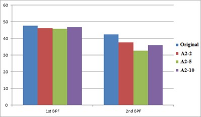
2nd BPF | 42.5 | 37.7 | –4.8 | 32.6 | –9.8 | 35.9 | –6.5 |
Fig. 5 shows the comparison of characteristic frequency between the first (A1) and the second (A2) resonator with the original fan. From the observation of noise reduction generated by resonators designed for different characteristic frequencies, a consistent reduction on the frequency spectrum is found for the in-line fans installed with resonators. Especially, as indicated in Fig. 5(a), the A1-5 fan has the better noise reduction effect on the first characteristic frequency (6.9 dBA). Due to the noise reduction on the first characteristics, the second characteristic frequency also decreases by means of harmonic resonance. Fig. 5(b) shows the comparison of characteristic frequency between the fan with the 2nd resonator and the original fan. Since the second resonator (A2) is designed for the noise reduction of second harmony (1,320 Hz); therefore, the pressure level of the first characteristic frequency doesn’t change remarkably. However, all resonators used here yield a significant noise reduction at the second BFF. From the simulation result, the best noise-reduction effect is reached at the cases of 5-resonator designs (A1-5 and A2-5).
Fig. 5Acoustic comparisons on the characteristic frequencies between the original inline fan and the fan equipped with A1 resonator and with A2 resonator
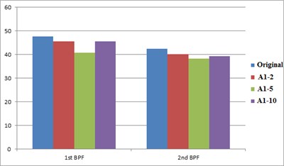
a) A1 resonator
b) A2 resonator
5. Conclusions
According to the results and discussions from previous sections, the influences on noise reduction induced by different parameters of Helmholtz resonator are evaluated and summarized from the calculated acoustic pressure level associated with the inline fans with resonators. These conclusions are listed in below.
The fluid and pressure fields associated with the in-line fan are simulated successfully and analyzed for the steady-state condition. Hence, the flow pattern and sound source can be identified clearly through the numerical flow visualization. In additions, the complete frequency spectrum including the barrow and board bands noises is calculated numerically by means of the combination of the FH-W and LES methods. Note that, from this unsteady aerodynamic noise field, the major noise sources are found around the fan discharge, the clearance between the housing, and the blade exit.
Owing to the design flexibility of Helmholtz resonator, the resonator size can be adjusted based on the geometrical limitation of this inline fan for its practical application. In this research, two resonators aimed at the first and the second harmonies are designed for fitting the geometrical limitation of this inline fan. Thereafter, the acoustic evaluations on these assembled fans are carried out systematically by the numerical tool. As a result, the maximum noise reductions on the 1st and the 2nd characteristic frequencies are obtained at 6.9 dBA and 9.8 dBA, respectively. Moreover, there is a minor noise-elimination effect found on the other harmonic frequency while the significant result appears on the designed characteristic frequency. However, all resonators used yield a significant noise reduction at the second BFF. From the simulation result, the best noise-reduction effects are reached at the 5-resonator designs (A1-5 and A2-5).
In conclusions, a comprehensive parametric study on Helmholtz resonator is carried out and summarized for attaining a design guideline for its application on the in-line fan. The accomplishment of this study provides a systematic scheme of noise reduction for an inline fan with the addition of Helmholtz resonator design.
References
-
Alster M. Improved calculation of resonant frequencies of Helmholtz resonators. Journal of Sound and Vibration, Vol. 1, Issue 24, 1972, p. 63-85.
-
Bies D. A., Hansen C. H. Engineering Noise Control: Theory and Practice. E&FN Spon, New York, NY, 1997.
-
Berank L. Noise and Vibration Control. Institute of Noise Control Engineering, Washington, DC, 1998.
-
Pierce A. Acoustic, an Introduction to its Physical Principle and Application. Acoustical Society of America, Woodbury, NY, 1991.
-
Parente C. A., et al. Hybird Active/Passive Jet Engine Noise Suppression Systems. NASA CR-1999-208875, NSL-RPT-98-002, 1999.
-
Han S. H. Sound Reduction by a Helmholtz Resonator. Thesis, Lehigh University, 2008.
-
Han S. S., Rhim Y. C. Noise-level reduction of a slim-type optical disk drive using the idea of a Helmholtz resonator. Transactions on Magnetics, Vol. 45, 2009, p. 2217-2220.
-
ANSYS Fluent User’s Guide, Version 14.5. ANSYS Inc., 2012.
-
Hinze J. O. Turbulence. McGraw-Hill Publishing Co., New York, 1975.
-
Launder B. E., Spalding D. B. Lectures in Mathematical Models of Turbulence. Academic Press, London, New York, 1972.
-
Smirnov R., Shi S., Celik I. Random flow generation technique for large eddy simulations and particle-dynamics modeling. Journal of Fluids Engineering, Vol. 123, 2001, p. 359-371.
-
Uranga A., Persson P., Drela M., Peraire J. Implicit large eddy simulation of transitional flows over airfoils and wings. 19th AIAA Computational Fluid Dynamics, San Antonio, Texas, 2009.
About this article

