Abstract
Finite element and boundary element models of the standard wheel, damping wheels and S-type damping wheels were established and compared. The radial vibration and axial vibration of the standard wheel could be reduced to decrease the vibro-acoustic radiation. Regarding damping wheels and S-type damping wheels, the coupling between the radial vibration and axial vibrations of 1 pitch circle could be reduced to decrease the radiation noise. The vibration acceleration in the tread, rim and web plate was significantly improved after applying damping in the standard wheel. If the web plate was changed into S-type structure, the vibration acceleration of the wheel at three positions was further reduced. The radiation noise of S-type damping wheels was significantly improved. The radiation noise of the web plate was significantly greater than that of the tread, which was caused by the larger radiation area of the web plate.
1. Introduction
Common noises of the high-speed train were divided into wheel-rail noises, pantograph noises, traction noises and aerodynamic noises. As shown in Fig. 1, the aerodynamic noise would be the main source of noises when the train speed was more than 300 km/h, which played important impact on the noise of the high-speed train. The traction noise was related to the traction devices of the train, which was the primary source of noises when the train speed is less than 30 km/h. Nevertheless, its impact was significantly reduced along with the increasing speed of the train. In the speed range of 50 km/h-200 km/h, the wheel-rail noise was the dominant noise source of the train, which played a great impact on the noise generated from the intercity high-speed train and urban rail transit. Furthermore, the rail noise was related to the structure of the rail and the brake noise was relevant to the brake method of the train, but their noises were lower than that of the wheel-rail noise. Therefore, the research and control of wheel-rail noises were of important significance in solving the railway noise problem.
The wheel-rail noise was mainly divided into the rolling noise, gear whine noises and wheel-rail impact noises [1, 2]. Due to the extremely large damping of wheel materials, about 10-4, the damping of mechanical system was a most critical factor for vibration attenuation if the resonance of the mechanical structure was appeared [3-6]. Therefore, the vibro-acoustic radiation of the wheel would be effectively reduced by increasing wheel damping. In the actual operation of the train, a certain additional contact damping on the wheel was generated from the rolling contact state between the wheel and rail. Generally, the contact damping makes the wheel damping increase from 10-4 to 10-3. Therefore, the increased wheel damping must be greater than the wheel itself and the additional damping generated from the wheel-rail contact. As a result, it would inhibit wheel and vibro-acoustic radiation effectively [7, 8].
Constrained damping technology was an effective program for the vibration suppression and noise reduction, which was widely used in the low-noise wheel of the train. A thin layer of high-damping viscoelastic material was pasted between the wheel and a rigid constraining layer. Since the viscoelastic damping layer was pasted between the basic layer and constraint layer, it was thus called constrained damping technology. The wheel with the constrained damping treatment of web plate, as studied by JONES [9], was applied and calculated, indicating that the wheel rolling noise of the wheel was reduced about 3 dB. In the experiment of Italy ETR500 high-speed train, the aluminum plate with the thickness of 1mm was applied as the constrained damping of the constraint layer to treat the wheel, indicating that the rolling noise was reduced about 4 dB-5 dB when the speed was between 200 km/h-300 km/h. Based on the multi-objective optimization, the constrained damping treatment was conducted on the wheel whose cross-sectional area was optimized, as studied by BRACCIALI [10, 11], the simulation calculation was applied, finding that the method made the wheel rolling noise reduce by 10 dB.
The metal plate with the thickness of 1mm was designed in RONA project, which was mounted on the wheel plate to shield its radiation noise. As shown from the test result, at the speed of 150 km/h and 300 km/h respectively, the vibro-acoustic radiation of the web plate shielding wheel was reduced by 5 dB and 6 dB compared with that of the standard wheel [12]. The similar web plate shielding device in the SILENT project was mounted on a wheel with optimized shape, which could reduce the wheel radiation noise by 8dB compared with standard wheels [13]. Combining the advantages of web plate shielding wheel and constrained damping wheel, Brunel developed a noise damping device for the web plate of the train wheel [14]. As indicated from the simulation result, the rolling noise generated from the operating high-speed train wheel could be effectively reduced by the noise damping device of the web plate.
Fig. 1Changes of noises with the operational speed [15]
![Changes of noises with the operational speed [15]](https://static-01.extrica.com/articles/17170/17170-img1.jpg)
Through the combination of experiment and numerical simulation, the vibro-acoustic radiation of the standard wheel, damping wheels and S-type damping wheels were studied in the paper and some meaningful conclusions were obtained, which provided some reference for the design of low-noise wheel.
2. Principles of damping wheels
Combined with the advantages of web plate shielding wheel and constrained damping wheel, the damping wheel could reduce the vibration and simultaneously shield the radiation noise in the web plate area.
The installation of shielding plate in wheel plate area was equivalent to control the radiation noise of wheel plate area in sound propagation path. Acoustic waves had passed through the intermediate layer [16-21], as shown in Fig. 2.
The transmission sound intensity and incident sound intensity, namely transmission factor of sound intensity [22-24], was shown as below:
In Eq. (1), is transmission sound intensity, is incident sound intensity, is thickness, and are the characteristic impedance of the two media, is wave number.
Fig. 2Schematic diagram of web plate shielding and damping wheel
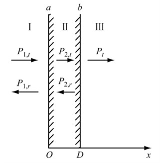
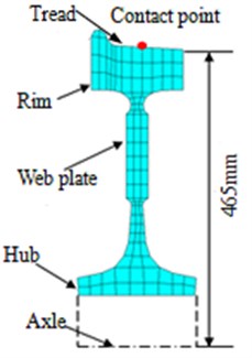
Fig. 3Cross-sectional diagram of wheels
As shown in Eq. (1), when the acoustic waves passed through the intermediate layer, the transmitted wave was not only related with characteristic resistance and of the two kinds of media, but with ratio concerning the intermediate layer thickness to the propagation wavelength.
The viscoelastic damping material was a high-molecular polymer material with the characteristics of both viscous liquid and elastic solid. If the material was deformed under the alternating stress, some energy could be stored like potential energy, while the remaining energy was dissipated and transferred into heat.
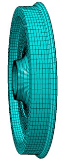
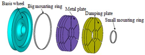
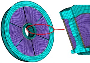
The wheel structure was comprised of tread, rim and web plate, respectively, as shown in Fig. 3. The unilateral web plate shielding damper was composed by six sector damping structures with the equant angle of 60°. Each sector damping structure was consisted of four layers of metal panels and three layers of damping materials. Both had the thickness of 2 mm and ZN03 type was selected as the damping material in the paper. The metal constraint layer and damping layer were positioned by special tooling, then adhered mutually and solidified into fixed shapes, as shown in Fig. 4.
Fig. 4Schematic diagram of damping wheels
3. Modal calculation and experimental verification of three kinds of wheels
Three web plates of wheels, namely standard wheels, damping wheels and S-type damping wheels, were given modal analysis, whose geometric shapes were shown in Fig. 5.
According to the geometric shapes of three web plates of wheels, the structural finite element model was obtained and presented in Fig. 6. The hexahedral elements were applied by the three kinds of wheels, and there were 2035, 2165 and 2378 elements in three kinds of wheels respectively. Additionally, the corresponding nodes were 2145, 2398 and 2507. The center hole in three kinds of wheels was fixed to simulate the actual situations. Lanzos algorithm was finally used to calculate the natural frequency and modals of wheels. The wheel materials had the elasticity modulus of 210 GPa, Poisson’s ratio of 0.3, and density of 7800 kg/m3.
Fig. 5Three web plates of wheels
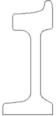
a) Standard wheels
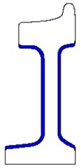
b) Damping wheels
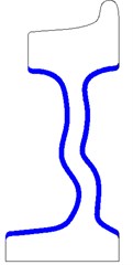
c) S-type damping wheels
Fig. 6The structural finite element model of wheels
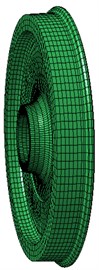
a) Standard wheels

b) Damping wheels
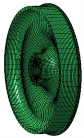
c) S-type damping wheels
The relatively complex finite element model would be caused by the damping applied on the wheel structure, which should necessarily be verified through experiments. As shown in Fig. 7, the wheel was conducted constrained modal experiment. The center of the wheel was fixed, and an acceleration sensor was used to test the vibration response of the wheel. Data collection equipment was used to obtain the vibration response, and it was imported into Pulse to be processed. The experiment was conducted by means of multi-point excitation and single-point response. The acceleration sensor was arranged on the position which has a serious structural response. Each excitation point was hit for three times. Frequency response function which has a good consistency was selected to be fit. Finally, the modal of the wheel can be obtained. The numerical modal was compared with the experimental modal as Table 1. As shown in Table 1, a relative small error was existed between the experimental and numerical results, thus demonstrating that the accuracy requirement could be satisfied by the finite element model, thus applicable for subsequent calculations.
The numerical simulation modal of the wheel could be extracted based on the above finite element model. The vibration modal of the wheel was similar to that of the disc, including in-plane radial vibration modal, circumferential vibration modal and out-of-plane axial vibration modal. The in-plane vibration can be represented by pitch diameter, namely radial modal and circumferential modal ; the out-of-plane vibration modal was written as , wherein represented the number of pitch circle and was the number of pitch dimeter. The pitch diameter referred to one or multiple diameters passing through the center of a plate in the vibrational process, whose diameter was remained as 0. The pitch circle was one or multiple concentric circles of the boundary circle in the vibrational process, whose displacement was remained as 0. The modal shapes and natural frequencies of the three kinds of wheels were shown from Fig. 8-Fig. 10. As known from the above analysis, the radial vibration and axial vibration of the standard wheel could be reduced to decrease the vibro-acoustic radiation. Concerning straight damping wheel and S-type damping wheel, the coupling of radial vibration and axial vibration of 1 pitch circle could be reduced to decline the sound radiation.
Fig. 7The modal experiment of the wheel
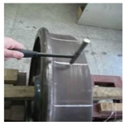
a) Vertical excitation
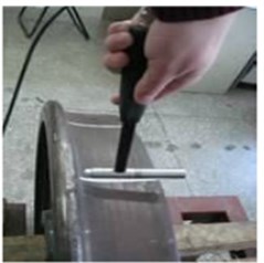
b) Lateral excitation
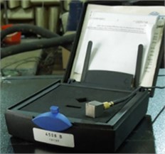
c) Acceleration sensor
d) Data collection equipment
Fig. 8Modes of straight standard wheels
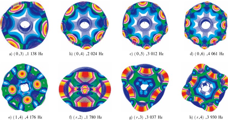
Fig. 9Modes of straight damping wheels
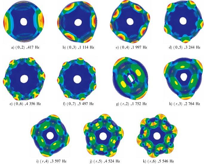
Fig. 10Modes of S-type damping wheels
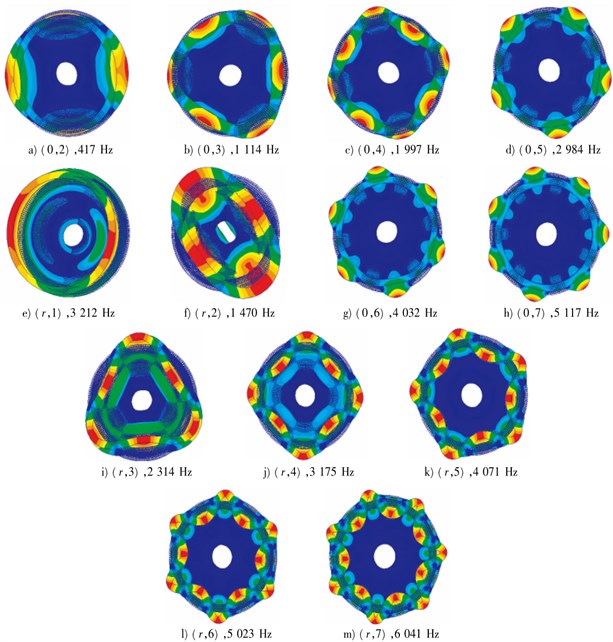
Table 1Comparison of the experimental modal and simulation modal
Order | Simulation value / Hz | experimental value / Hz | Relative error / % |
1 | 134.7 | 138.2 | –2.51 |
2 | 192.8 | 190.5 | 1.21 |
3 | 356.1 | 354.7 | 0.39 |
4 | 417.4 | 413.5 | –0.93 |
5 | 1114.0 | 1112.2 | –0.16 |
6 | 1287.8 | 1280.4 | 0.57 |
4. Transient dynamic analyses of three kinds of wheels
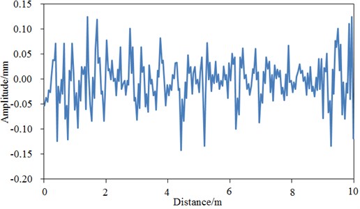
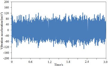
The vehicle-track coupling dynamic model and Sato spectrum were presented as shown in Fig. 11 and Fig. 12. As a whole system, the vehicle and slab track were established a vertical coupling dynamics model. The differential equations regarding the vibration of the upper vehicle system and lower rail system were listed, and the time-history curve of wheel-rail force was obtained by the calculation of numerical simulation. CRH3 vehicle and CRTS slab track structure were applied, with the vehicle axle load of 14t, rail of P60, train speed of 200 km/h, and other parameters from references [25]. The time-history curve of vertical wheel-rail force was shown in Fig. 13(a). It could be seen that the vertical wheel-rail force of a wheel was fluctuated around 70 kN.
Fig. 11The vehicle-track coupling dynamic model
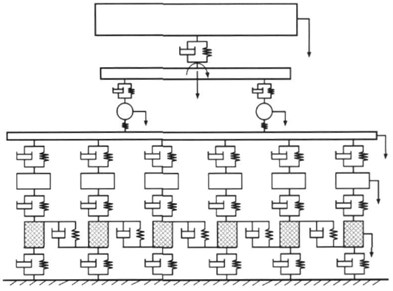
Fig. 12Sato spectrum
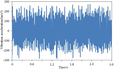
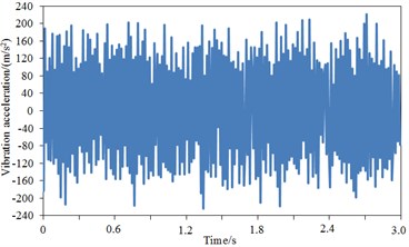
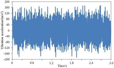
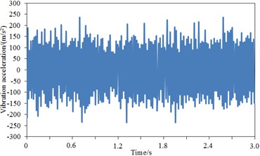
The simulated wheel-rail force was applied on the wheel-rail contact point, so as to study the transient dynamic characteristics of the wheel. Points on the tread, rims and web plates were selected to extract the time-history curve of their vibration accelerations, whose results were shown in Fig. 13.
The comparison result regarding vibration acceleration responses of standard wheel tread and damping wheel tread was shown in Fig. 13(b)-Fig. 13(d). It was shown that the maximum vibration acceleration was –291.3 m/s2 for the standard wheel tread, –235.1 m/s2 for the damping wheel tread, and –198.1 m/s2 for S-type damping wheel tread, thus demonstrating that the vibration of the standard wheel could be effectively attenuated after applying damping, and the tread vibration could be further reduced by the structural changes of wheel plate. During 3 s, the vibration acceleration of the damping wheel tread was significantly decreased compared with the standard wheel tread since the vibration could be attenuated effectively by the applied damping of the wheel plate, then transferred into heat energy and dissipated. The comparison result regarding vibration acceleration responses of standard wheel rim and damping wheel rim was shown in Fig. 13(e)-Fig. 13(g). It was shown that the maximum vibration acceleration was –244.2 m/s2 for the standard wheel rim, 201.1 m/s2 for the damping wheel rim, and 162.5 m/s2 for S-type damping wheel rim, thus demonstrating that rim vibration acceleration was improved significantly after applying damping in the wheel. Similarly, during 3 s, the vibration acceleration of the damping wheel rim was significantly decreased compared with the standard wheel rim. The comparison result regarding vibration acceleration responses of standard wheel plate and damping wheel plate was shown in Fig. 13(h)-Fig. 13(j). It was shown that after the stabilization of the vibration, the maximum vibration acceleration was –240.2 m/s2 for the standard wheel plate, –194.6 m/s2 for the damping wheel plate, and –132.1 m/s2 for S-type damping wheel plate. During 3 s, the vibration acceleration response of the damping wheel plate was significantly decreased with greater amplitude. Additionally, as found from the comparison regarding vibration accelerations of tread, rim and web plate, the vibration accelerations of tread were significantly larger than that of rim and web plate, which was because the vibration acceleration of tread was directly reflected by the rail irregularity due to the direct contact between tread and rail, while the vibration accelerations of rim and web plate were resulted from the tread. The wheel tread noise was mainly radiated vertically, basically going upward or spreading through the body to the compartment, thus increasing the interior noise and reducing the noise to the surrounding environment. The wheel plate noise was mainly radiated to the surrounding environment, which was one of the sources of environmental noise. Therefore, the vibration response of the web plate was significantly reduced, thus decreasing its radiation noise to the environment and improving the operating environment of the train. Furthermore, as known from the structure of the wheel, the web plate had much greater area than the tread; though the vibration acceleration of the web plate was small, its radiation area was large, which would cause the web plate to be the most serious area of radiation noise.
5. Radiation noise analyses of three kinds of wheels
Based on the above analysis of vibration response, the radiation noise of the wheel could be further studied. The vibration response result was used as the boundary condition, acoustic BEM [26-29] software Virtual.Lab was applied, and direct BEM was employed to calculate the sound radiation of the wheel. When the computational process was conducted, the air density was 1.21 kg/m3, the propagation speed of sound in the air was 340 m/s, the frequency range was 0 Hz-3000 Hz, and the step length was 50 Hz. The element had a great influence on the analytical accuracy of sound radiation. Generally, the element size of acoustic boundary element should have the length shorter than 1/6 of the minimal wavelength for the computational frequency and be consistent. The computational accuracy cannot be improved by the very small local elements because the precision of fluid model was controlled by multiple elements. S-type damping wheel was taken as the example to extract the outer surface of its geometrical model and generate the corresponding elements. The boundary element model was shown in Fig. 14. The model had 2103 quadrilateral elements and 1698 nodes all together. The center hole in the geometrical model was closed. The computational result of the structural finite element model was imported into Virtal.Lab and mapped into the boundary element model. As a result, the boundary element model can obtain the whole characteristics of the finite element model, and the vibro-acoustic coupling was achieved.
Fig. 13Excitations forces and vibration accelerations of three kinds of wheels
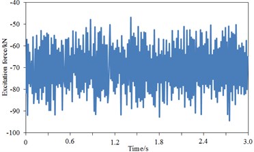
a) Excitation force
b) Tread – standard wheel
c) Tread – damping wheel
d) Tread – S-type damping wheel
e) Rim – standard wheel
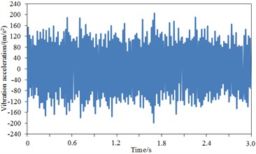
f) Rim – damping wheel
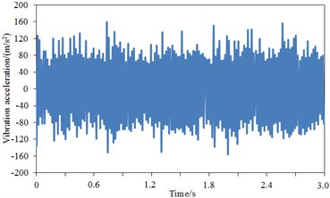
g) Rim – S-type damping wheel
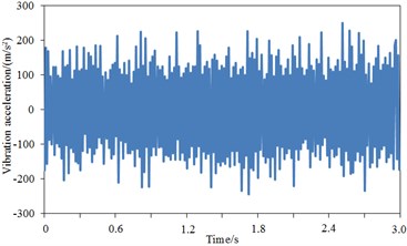
h) Web plate – standard wheel
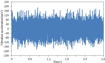
i) Web plate – damping wheel
j) Web plate – S-type damping wheel
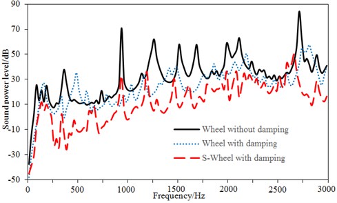
The field point models of three planes were established to observe the radiation noise distribution in various regions, as shown in Fig. 15. The vibration acceleration of wheels was imported into Virtual.Lab software and mapped to the acoustic boundary element model. Therefore, the structural vibration acceleration response would be obtained by the acoustic boundary element mesh, ultimately realizing the coupling between structure and acoustics. The radiation sound power levels of three kinds of wheels could be obtained based on the above calculation process and method, as shown in Fig. 16. It was shown from Fig. 16 that radiation sound power of standard wheels had the maximum value of 85.1 dB and minimum value of –39.2 dB, with the difference of 124.3 dB. Many obvious peaks were appeared in the whole frequency spectrum. The damping wheel had the maximum radiation sound power of 52.2 dB and minimum value of –49.2 dB, with the difference of 101.4 dB. Though many obvious peaks were appeared in the whole frequency spectrum, however, it was unobvious as the standard wheel. S-type damping wheels had the maximum radiation sound power of 47.8 dB and minimum value of –47.4 dB, with the difference of 95.2 dB. Compared with the damping wheel, its radiation sound power throughout the whole frequency spectrum was improved at most frequency points, and it was enlarged at only a small part of frequencies.
Fig. 14Boundary element models of wheels
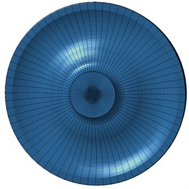
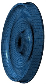
Fig. 15Observation points of radiation noises of wheels
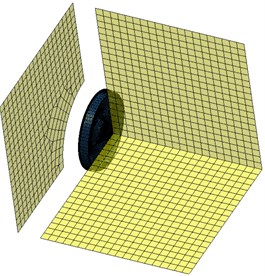
Fig. 16Comparison of radiation noises of three kinds of wheels
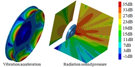
The sound pressure and vibration acceleration contours of S-type damping wheels were extracted at 300 Hz, 1000 Hz, 1500 Hz and 2000 Hz, whose results were shown in Fig. 17. It was shown that the noise of the tread was mainly transmitted in the vertical direction, eventually into the train. However, the noise of the web plate was mainly transmitted in the horizontal direction, thus increasing the noise of the operating environment. Moreover, a clear corresponding relation was existed between the radiation sound power and vibration accelerations of the wheel. For example, the vibration acceleration of some areas was relatively large, and the radiation noise near these areas was also larger. As can be seen from the figure, the radiation noise of the web plate was obviously much larger than that of the tread, which was caused by the relatively larger radiation area of the web plate.
Fig. 17Vibration acceleration and radiation noise contour of S-type damping wheel
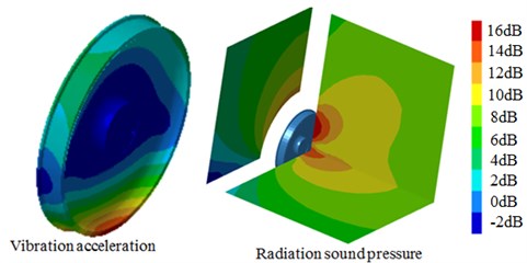
a) 300 Hz
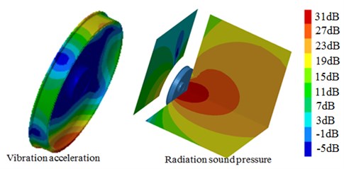
b) 1000 Hz
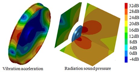
c) 1500 Hz
d) 2000 Hz
6. Conclusions
1) Finite element models of the standard wheel, damping wheels and S-type damping wheels were established, and their modals were compared with the corresponding experiment results. As shown from the result, the relative error was very small and the model accuracy was high, thus meeting the requirements.
2) Modes of three kinds of wheels were extracted and analyzed. The radial vibration and axial vibration of the standard wheel could be reduced to decrease the vibro-acoustic radiation. Regarding damping wheels and S-type damping wheels, the coupling between the radial vibration and axial vibrations of 1 pitch circle could be reduced to decrease the radiation noise.
3) The vibration acceleration responses of three kinds of wheels were calculated. After applying damping in the standard wheel, the vibration acceleration in the tread, rim and web plate was significantly improved. If the web plate was changed into S-type structure, the vibration acceleration of the wheel at three positions was further reduced. Moreover, the vibration acceleration of the tread was significantly greater than that of the rim and web plate.
4) The acoustic boundary element model of the wheel was established based on vibration response analysis to calculate the radiation noise. Compared with the other structures, the radiation noise of S-type damping wheels was significantly improved. Besides, the noise of the tread was mainly transmitted in the vertical direction, eventually into the vehicle. However, the noise of the web plate was primarily transmitted externally in the horizontal direction, thus increasing the noise of the operating environment. Additionally, an obviously corresponding relation was existed between the radiation sound power and vibration accelerations of the wheel. For example, the vibration acceleration of some areas was relatively large, and the radiation noise near these areas was also larger. The radiation noise of the web plate was significantly greater than that of the tread, which was caused by the larger radiation area of the web plate.
References
-
Jin X. S., Zhang X. S., Zhang J., et al. Mechanics in performance of wheel-rail. Journal of Mechanical Strength, Vol. 27, Issue 4, 2005, p. 408-418.
-
Rao M. D. Recent applications of viscoelastic damping for noise control in automobiles and commercial airplanes. Journal of Sound and Vibration, Vol. 262, Issue 3, 2003, p. 457-474.
-
Li J. Q., He S. Q., And Ming Z. An intelligent wireless sensor networks system with multiple servers communication. International Journal of Distributed Sensor Networks, Vol. 7, 2015, p. 1-9.
-
Zhu S. J., Zheng Y. F., Fu Y. M. Analysis of non-linear dynamics of a two-degree-of-freedom vibration system with non-linear damping and non-linear spring. Journal of Sound and Vibration, Vol. 271, Issue 1, 2004, p. 15-24.
-
Lin Q. Z., Zhu Q. L., Huang P. Z., Chen J. Y., Ming Z., Yu J. P. A novel hybrid multi-objective immune algorithm with adaptive differential evolution. Computers and Operations Research, Vol. 65, 2015, p. 95-111.
-
Trindade M. A., Benjeddou A., Ohayon R. Piezoelectric active vibration control of damped sandwich beams. Journal of Sound and Vibration, Vol. 246, Issue 4, 2001, p. 653-677.
-
Wei W., Fan X., Song H., et al. Imperfect Information dynamic Stackelberg game based resource allocation using hidden Markov for cloud computing. IEEE Transactions on Services Computing, 2016.
-
Thompson D. Railway Noise and Vibration: Mechanisms, Modelling and Means of Control. Elsevier, 2008.
-
Jones C. J. C., Thompson D. J., Frid A., et al. Design of a railway wheel with acoustically improved cross-section and constrained layer damping. Proceedings of Internoise, Vol. 2, 2000, p. 673-678.
-
Bracciali A., Bianchi M. Lucchini CRS Syope® damped wheels noise qualification. 13th International Wheelset Congress, Roma, Italy, Vol. 17, 2001, p. 21-9.
-
Cervello S., Donzella G., Pola A., et al. Analysis and design of a low-noise railway wheel. Proceedings of the Institution of Mechanical Engineers, Part F: Journal of Rail and Rapid Transit, Vol. 215, Issue 3, 2001, p. 179-192.
-
Thompson D. J., Gautier P. E. Review of research into wheel/rail rolling noise reduction. Proceedings of the Institution of Mechanical Engineers, Part F: Journal of Rail and Rapid Transit, Vol. 220, Issue 4, 2006, p. 385-408.
-
Hemsworth B., Gautier P. E., Jones R. Silent freight and silent track projects. Proceedings of Internoise, 2000, p. 714-719.
-
Brunel J. F., Dufrénoy P., Demilly F. Modelling of squeal noise attenuation of ring damped wheels. Applied Acoustics, Vol. 65, Issue 5, 2004, p. 457-471.
-
Licitra G. Railway Noise in Urban Areas: Possible Source Noise Reduction Measures. UIC, Pisa, 2006.
-
Guyomar D., Richard T., Richard C. Sound wave transmission reduction through a plate using piezoelectric synchronized switch damping technique. Journal of Intelligent Material Systems and Structures, 2007.
-
Zhu Z., Xiao J., Li J. Q., et al. Global path planning of wheeled robots using multi-objective memetic algorithms. Integrated Computer-Aided Engineering, Vol. 22, Issue 4, 2015, p. 387-404.
-
Liu G. R., Cai C., Lam K. Y. Sound reflection and transmission of compliant plate-like structures by a plane sound wave excitation. Journal of Sound and Vibration, Vol. 230, Issue 4, 2000, p. 809-824.
-
Wei W., Xu Q., Wang L., et al. GI/Geom/1 queue based on communication model for mesh networks. International Journal of Communication Systems, Vol. 27, Issue 11, 2014, p. 3013-3029.
-
Lin Q., Wong K. W., Chen J. An enhanced variable-length arithmetic coding and encryption scheme using chaotic maps. Journal of Systems and Software, Vol. 86, Issue 5, 2013, p. 1384-1389.
-
Hopkins C. Statistical energy analysis of coupled plate systems with low modal density and low modal overlap. Journal of Sound and Vibration, Vol. 251, Issue 2, 2002, p. 193-214.
-
Du G. H. Acoustic Basis. Nanjing University Press, 2012.
-
Chen J. Y., Lin Q. Z., Hu Q. B. Application of novel clonal algorithm in multiobjective optimization. International Journal of Information Technology and Decision Making, Vol. 9, Issue 2, 2010, p. 239-266.
-
Wei W., Yang X. L., Zhou B., et al. Combined energy minimization for image reconstruction from few views. Mathematical Problems in Engineering, Vol. 16, Issue 7, 2012, p. 2213-2223.
-
Chen G. Vertical-lateral model of vehicle-track coupling system and its verification. Journal of Vibration and Shock, 2001.
-
Cheng A. H. D., Cheng D. T. Heritage and early history of the boundary element method. Engineering Analysis with Boundary Elements, Vol. 29, Issue 3, 2005, p. 268-302.
-
Chen J., Lin Q., Shen L. L. An immune-inspired evolution strategy for constrained optimization problems. International Journal on Artificial Intelligence Tools, Vol. 20, Issue 3, 2011, p. 549-561.
-
Fuchs M., Kastner J., Wagner M., et al. A standardized boundary element method volume conductor model. Clinical Neurophysiology, Vol. 113, Issue 5, 2002, p. 702-712.
-
Franzoni L. P., Bliss D. B., Rouse J. W. An acoustic boundary element method based on energy and intensity variables for prediction of high-frequency broadband sound fields. The Journal of the Acoustical Society of America, Vol. 110, Issue 6, 2001, p. 3071-3080.
About this article

