Abstract
The present paper discusses results of simulation tests conducted using an identified dynamic model of a laboratory station with gear transmissions. The dynamic forces found to be acting in bearing assemblies were assumed as input functions for the purposes of studies of the numerical housing models developed. Using fine-tuned modal housing models in the analysis of the design solutions applied allowed for choosing appropriate arrangement of the transmission ribbing. By analyzing the shape of the ribbing layout envisaged as well as its structural characteristics (height and width of ribs), one could choose a housing of reduced vibroactivity and mass.
1. Introduction
Basic noise-related health and safety requirements for machine engineering have imposed a specific requirement that the noise emitted by machinery must already be decreased on the designing stage. In line with the foregoing, a machine should be designed in a manner ensuring that the hazards due to noise emission are minimised, bearing in mind the state of the art and the available methods and means. What proves to be particularly important in this respect is the minimisation of power of vibroacoustic signal sources. Housings of machines, besides ensuring appropriately compact structure, strength and rigidity, should also provide for sufficient vibration damping. All material engineering and design related efforts which improve the aforementioned properties of housings are beneficial from the perspective of the noise emitted by machines.
While components of power transmission systems for machines are being designed, some of the goals pursued are minimisation of the vibrations they generate and reduction of their mass. In order to design an appropriate power transmission system or its components, characterised by reduced mass and vibroactivity, a multitude of factors must be taken into consideration. On account of the costs related to testing of real objects, active experiments are very often substituted by simulation studies conducted using dedicated software, based on suitable models. The foregoing enables a comprehensive analysis of the research assumptions adopted, and it is economically sound by limiting the scope of the necessary experimental tests to the required minimum.
Vibroactivity of gear transmissions depends on the value of input functions primarily caused by the meshing of gears and the resonance characteristics of the housing, bearing assemblies as well as the gears themselves. The studies conducted to date imply that the main reason why the transmission housing generates noise [1-3] is being excited to oscillate by shafts and bearings, and not the impact of the acoustic pressure changes inside the transmission. The energy transferred by shafts and bearing assemblies corresponds to 90 up to 95 % of the total vibration energy transferred to the housing [4-6]. Vibrations and noise are also generated in gear transmissions because of poor technical condition of the latter. The process of progressing wear of the transmission components is accompanied by intensification of the said phenomena. The cause and effect relationship between wear and vibrations as well as noise is the very foundation of vibroacoustic diagnostics. Furthermore, defects of the aforementioned elements (e.g. rolling bearings) also contribute to the generation of resonant vibrations of structural transmission components.
Under industrial conditions, gear transmissions generate very high levels of acoustic power [2, 5]. It is caused by high values of power transferred by transmissions as well as characteristics of the coefficient of efficiency of mechanical energy conversion into acoustic energy. Both the bench tests and the industrial tests conducted to date have provided grounds for many methods currently used for minimisation of vibroactivity in gear transmissions. Among them, one should mention the application of the gear tooth profile modification, vibration damping elements or active vibration reduction methods. In order to attain the same goal, one may also use gears manufactured according to higher precision classes, skew bevel gears or high tooth gears, and replace rolling bearings with slide bearings. The purpose of reduction of transmission vibroactivity may also be pursued through minimisation of external input functions affecting transmissions in the power transmission system, appropriate selection of its parameters as well as correct choice of structural characteristics of its housing.
It is possible to significantly reduce noise emission from gear transmissions by minimising vibrations in the meshing zone, decreasing efficiency of transmission of these vibrations and reducing the emission level of housings [6]. Consequently, reduction of vibroacoustic activity of gear transmissions requires a detailed analysis of the mechanism governing the generation of dynamic forces in the meshing being the source of vibrations, transmission of these vibrations to the emission point as well as various aspects related to sound emission through the housing [6].
Assuming that all input functions affecting the transmission may be substituted with a single force exciting the sound emitting surface, then the transmission noise power spectrum [5] depends on density of the surrounding medium , sound velocity in the medium, mean square value of vibration velocity of surface points, emission area exciting force spectrum, filtering characteristics of the transmittance function and an experimentally determined coefficient of emission, being characteristic of a specific transmission housing design solution . If one further assumes that the exciting force spectrum and the filtering characteristics of the transmittance function can be substituted with the vibration velocity spectrum, the acoustic power emitted by an oscillating surface may be derived from dependence:
Having analysed dependence (1), one may notice that in order to calculate the value of the transmission’s acoustic power, one must first establish the mean square value of vibration velocity of measurement points on its housing, assuming constant values of the remaining quantities. For purposes of bench and simulation tests, the following dependence was assumed as the measure of vibroactivity of housings:
where: – vibration velocity of the th measurement point at instant , – the number of samples measured during the analysis time, – the number of measurement points.
Under the bench tests and the numerical studies conducted to determine the impact of selected structural characteristics of ribbing of gear transmission housings on their vibroactivity, it was assumed that reduction of the latter is only possible through an appropriate choice of structural characteristics of the ribbing solution assumed for the gear transmission housing.
2. Tests validating numerical models of gear transmission housings
In the course of the bench tests discussed, three one-stage skew bevel gear transmissions were used, differing in terms of the housing ribbing [5]. In terms of the design, the housings were divided in the plane of the gears’ axes and made of welded 6 mm thick steel plates (Fig. 1). The first housing was made without additional ribbing (Fig. 1(a) – housing A), whereas another two were modified by adding, respectively, two ribs parallel to the shaft axes (Fig. 1(b) – housing B) and two ribs parallel as well as one rib perpendicular to the transmission shaft axes (Fig. 1(c) – housing ). The ribbed housings were manufactured assuming the following structural characteristics of ribs: height 30 mm, width 10 mm.
Fig. 1Housing: a) non-ribbed, b) with two ribs parallel to shaft axes, c) with two ribs parallel and one rib perpendicular to shaft axes [5]
![Housing: a) non-ribbed, b) with two ribs parallel to shaft axes, c) with two ribs parallel and one rib perpendicular to shaft axes [5]](https://static-01.extrica.com/articles/17168/17168-img1.jpg)
a)
![Housing: a) non-ribbed, b) with two ribs parallel to shaft axes, c) with two ribs parallel and one rib perpendicular to shaft axes [5]](https://static-01.extrica.com/articles/17168/17168-img2.jpg)
b)
![Housing: a) non-ribbed, b) with two ribs parallel to shaft axes, c) with two ribs parallel and one rib perpendicular to shaft axes [5]](https://static-01.extrica.com/articles/17168/17168-img3.jpg)
c)
Geometrical features of the geometrical models developed in the CAD environment correspond to dimensions of the actual housings (Fig. 2(a)). Based on three-dimensional geometrical models of transmission housings, their numerical models were created (Fig. 2(b)). These FEM models consist of ca. 29,000, 8-node solid elements. The largest dimension assumed, i.e. the element length, came to 6 mm, which corresponded to the housing wall thickness. On account of the material the actual housings were made of, the material assumed in the FEM models was the S235JR steel (Table 1). The numerical models thus developed comprised no welded joints, however, threaded joints for connecting the upper and the lower housing section were included.
Fig. 2Sample geometrical model of a non-ribbed housing
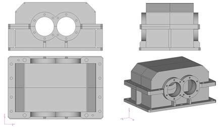
a) Geometrical
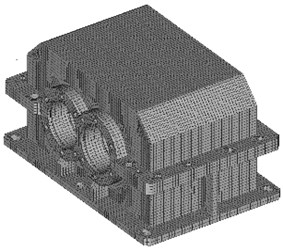
b) Numerical
Table 1Properties of the steel S235JR
Tensile modulus (GPa) | 210 |
Shear modulus (GPa) | 80 |
Poisson’s ratio | 0,3 |
Density (kg/m3) | 7850 |
The numerical simplifications assumed, connected with modelling of the actual housing structure, for instance, those related to modelling of welded and threaded joints, had caused that the results obtained from simulation calculations differed from the values established by experimental means. Consequently, it was necessary to improve the compatibility between the numerical housing model and the actual one. A numerical model is typically adjusted within the range of several initial free vibration frequencies, this being caused by the difficulty to identify higher free vibration frequencies and forms with regard to actual objects. Comparing the results obtained from numerical simulations and those of experimental measurements is the basic stage in the process of adjusting mathematical models. Modifications introduced in the numerical model based on such grounds make it possible to reassess the accuracy of the adjusted model and recognise the dynamic responses of the structure identified by way of simulations as accurate representations of the responses which would be measured if an actual object was studied.
In the process of identification of the above FEM models of housings A, B and F, experimental modal analysis was applied [7, 8]. For this purpose, free vibration frequencies of the actual gear transmission housings were measured [5, 9]. Maximum differences between the values of free vibration frequencies of the housings tested and their numerical models came to 5.5 %. In further steps of the analysis, a comparison between individual vibration forms of transmission housings and their FEM models was conducted in resonant states, thus obtaining convergence of displacements. What could also be verified was the compatibility between the FEM models of transmission housings and the actual ones. For that purpose, the MAC coefficient (Modal Assurance Criterion) was applied [8]. The MAC values obtained for the assumed transmission housing design solutions, namely without ribbing and with ribbing partially removed, confirmed the conformity between the FEM models developed and the actual objects.
In order to verify the adjusted FEM transmission housing models thus developed, additional bench tests and numerical studies were conducted [10, 11] with the purpose of establishing vibration velocity values at six measurement points arranged on the upper transmission housing cover (Fig. 3).
For purposes of the experimental tests, a circulating power test rig illustrated in Fig. 4, featuring gauges and recoding apparatus, was used. The transmissions subject to testing were coupled with a closing transmission by means of a set of connecting shafts, a torsional shaft and a tightening coupling used for loading. The closing transmission had been isolated from the transmission subject to testing by installing dedicated acoustic screens of suitable design matching the testing needs.
Normal velocities of the transmission housing vibrations were measured by a contact-free method using the Ometron VH300+ laser vibration meter. The signals being measured were recorded by means of the National Instrument NI 4472 data acquisition board and a laptop featuring the LabView 8.6 software. The recorded vibroacoustic signals of vibration velocity were analysed in the Matlab-Simulink environment. In the course of the bench tests, a series of measurements was conducted on unit loads of Q, which respectively equalled: 1.23, 2.15, 3.02 and 4.09 MPa, and on two rates of the gear shaft rotation coming to 900 and 1,800 rpm. On account of the considerable impact of oil temperature on vibration values, the measurements were conducted under conditions of steady gear transmission oil temperature equalling 45±5°C.
Fig. 3Arrangement of points P1-P6 for vibration velocity measurements on the housing
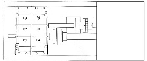
a) Stationary study
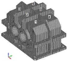
b) Simulation study
The simulation studies for the chosen six measurement points (Fig. 3(b)) were conducted using the adjusted FEM housing models. The simulation input data were spectra of the forces acting inside bearings, established with reference to the identified dynamic gear transmission model [12, 13], assuming the unit load value of 2.5 MPa and two rates of rotation, i.e. 900 and 1,800 rpm.
Fig. 4Test stand with recording devices and measuring instruments [5, 10]
![Test stand with recording devices and measuring instruments [5, 10]](https://static-01.extrica.com/articles/17168/17168-img8.jpg)
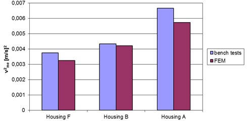
Fig. 5 illustrates changes to the values of the vibroactivity measure proposed (dependence 2) for the housing design solutions analysed, as determined in experimental and numerical studies. The conformity established between the results of bench tests and simulation studies of the three gear transmission housing solutions confirmed the correctness of the FEM models previously developed (Fig. 5).
Fig. 5Comparison of vibroactivity measure vme2 established experimentally and numerically for the housings examined
3. Simulation studies of vibroactivity of gear transmission housings
For purposes of the vibroactivity assessment conducted for different housing design solutions, the assumed subject of analysis was the modification of only their upper covers. Based on the distributions and velocities established for surface (upper housing cover) vibrations in the areas of the highest vibration amplitude, an optimum ribbing arrangement was proposed, aimed at reduction of values of the foregoing quantities.
The numerical models developed for the analysed transmission housing ribbing design solutions have been characterised in Table 2. Using additional housing ribs and connecting pieces in the design solutions proposed leads to a corresponding increase in mass of the models developed. Fig. 6 illustrates percentage changes to the mass of the housings analysed compared to non-ribbed housings (housing A).
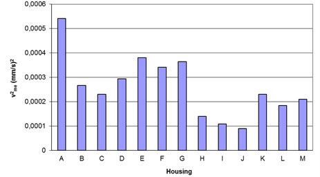
For all the housing models prepared, simulation studies were conducted in order to determine the influence exerted by the upper housing cover ribbing on the gear’s vibroactivity. On account of the time demand of simulation calculations, certain simplifications were adopted in preliminary studies, namely the input functions being assumed as unit pulses applied in bearing assemblies. By means of the Femap software, one could determine the relevant vibration velocity values at the selected six points of the housing covers (Fig. 3(b)). The computational values of measure (dependence 2) in the analysed range of frequency (up to 3.5 kHz) have been depicted in Fig. 7 for all the housing ribbing solutions studied.
The values of measure shown in Fig. 7 allow for making a choice of the most suitable ribbing solution for a reduced vibroactivity housing, assuming the criterion of the housing mass minimisation (Fig. 6). The largest reduction of the value was obtained by simultaneously adding two reinforcing ribs, both parallel and perpendicular to the shaft axes, along with connecting pieces between them (housings H, I, J – line 3, Table 2). As for the housings featuring two ribs parallel and three ribs perpendicular to the shaft axes (housings K, L and M – line 4, Table 2), one may also observe a considerable decline in the value of . However, as implied by Fig. 6, adopting such ribbing design solutions for housings entails an increase in their mass by ca. 11-16 %. And since a reduced vibroactivity housing solution was sought, it was assumed that the housing mass should not increase by more than 10 % compared to non-ribbed housing. Consequently, based on the results illustrated in Fig. 6 and 7, housings C and F advanced to further analysis. The mass of housing C increased by 5 %, and it displayed the largest reduction of measure in the group composed of housings B, C and D. Housing F, on the other hand, increased its mass by 8 % and displayed the largest reduction of measure in the group comprising housings E, F and G.
Fig. 6Changes in masses of the housings examined in per cent with reference to a non-ribbed housing
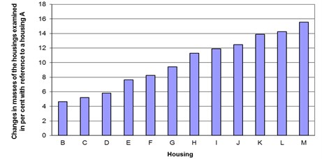
Fig. 7Values of measure vme2 depending on the housing ribbing layout in the frequency range envisaged, assuming one-time input in bearing assemblies
Having analysed the research results discussed in the literature [2-5] as well as those of the author’s own studies, it was determined that vibroactivity of gear transmission housings was also significantly affected by their structural characteristics (shape, height and width), besides the correct arrangement of ribs. In an attempt to define the optimum shape of ribs for the chosen housings, topology optimisation was applied [14, 15].
The purpose of the simulation calculations undertaken was to verify the possibility of modifying structural characteristics (shape) of housing ribs, at the same time, accounting for the criterion of minimisation of their mass (Maximize Stiffness&Reduce Volume). The calculations were based on the assumption that the change in the housing volume (mass) must not exceed 10 % (Percent Volume Reduct parameter). The only aspect analysed was the shape of upper covers of housings C and F. Therefore, the optimisation did not account for an option of changing the number of ribs and their positioning. What was also assumed was the invariability of dimensions of upper housing covers. Selected results obtained from the analysis, corresponding to successive iteration stages for the upper covers of housings C and F, have been collated in Table 3. In order to receive an accurate representation of the calculation results, Table 3 contains maps of upper covers instead of entire housings. For the fifteenth iteration (last line in Table 3), the areas which – as the analysis implies – may be removed or modified have been marked in purple colour. The red color applies to areas that should not be modified.
Table 2FEM models developed for the housing ribbing solutions subjected to preliminary studies
Housing A 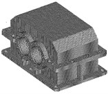 | |||
1 | Housing B 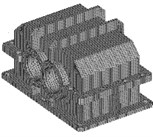 | Housing C 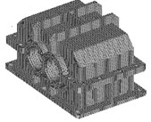 | Housing D 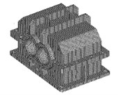 |
2 | Housing E 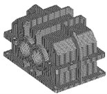 | Housing F 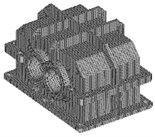 | Housing G 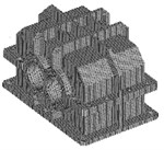 |
3 | Housing H 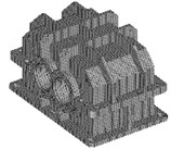 | Housing I 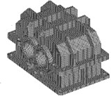 | Housing J 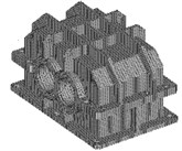 |
4 | Housing K 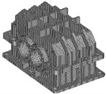 | Housing L  | Housing M 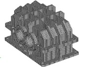 |
Having analysed the results compared in Table 3, one may claim that, in housing C, the connecting piece between ribs may be removed, whereas the bottom housing flange and the shape of ribs above bearings seats may be modified. The change assumed as the modification involved removal of the rib connecting piece only. A housing thus obtained received the shape of housing B which had previously been analysed. As for housing F, it was possible to modify the shape of the rib perpendicular to the gear axes as well as the bottom housing flange and the shape of ribs above bearings seats, whereas the only modification taken into consideration was the change of shape of the rib perpendicular to the gear axes.
Table 3Results of calculations for housings C and F
Number of iterations | Housing C | Housing F |
5 | 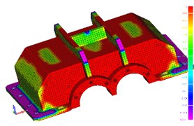 | 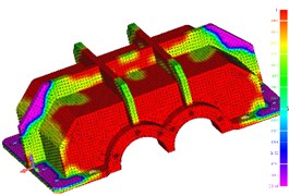 |
10 | 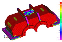 | 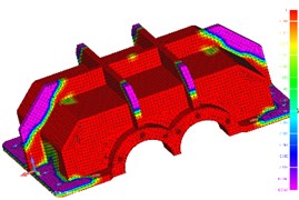 |
15 |  | 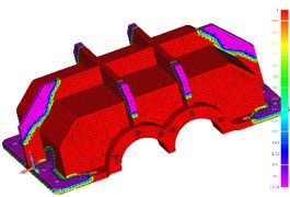 |
In housings C and F, the shape of ribs above the bearing seats was not modified, having previously assumed that sufficient rigidity of bearing seats must be maintained at points subject to the influence of input functions connected with the dynamic forces acting in bearing assemblies. Also the shape of bottom housing flanges was not modified, since they were intended for mounting of and coupling with the second part of the transmission housing.
Based on the analysis of the results thus obtained, new geometrical and numerical housing models were developed (Fig. 8) based on the modification of the design solutions previously assumed for the ribbing of housings C and F. The modified solutions of ribbing for housings C and F were respectively designated as C_1 and F_1.
Fig. 8Modified numerical models created
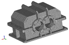
a) Housing C_1
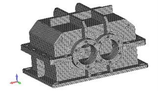
b) Housing F_1
In the simulation studies verifying the preliminary results illustrated in Fig. 7 for housings C, C_1, F and F_1, the input data assumed were spectra of the forces acting in bearings, previously determined using the identified dynamic gear transmission model. Moreover, normal values of vibration velocity were established (2279) at all points of the FEM models of upper housing covers. The mechanism of vibration inducing assumed in the models corresponded to the conditions typical of the actual transmission.
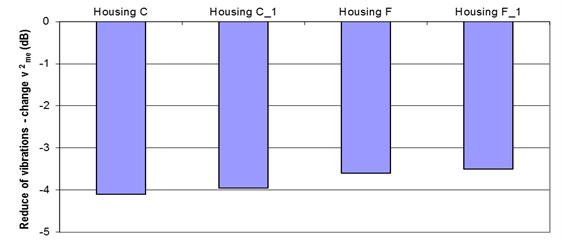
Fig. 9 shows changes in the value of in (dB) as compared with the housing prior to modification (housing A) for the upper transmission housing cover design solutions chosen for analysis, with the frequency ranging up to 3.5 kHz. Having analysed the results illustrated in Fig. 9, it was determined that the modifications assumed for housings C_1 and F_1 triggered changes in the value of comparable to those of housings C and F, while at the same time, their mass dropped owing to the ribbing modification.
Fig. 9Values of vibroactivity measure vme2 depending on the housing layout assumed with reference to housing A in the frequency range envisaged, expressed in dB
As a result of the foregoing, in subsequent tests conducted under the analysis of structural characteristics of ribs (height and width), the modified housing ribbing solution (i.e. housings C_1 and F_1) was taken into consideration. Different rib heights () and widths () were assumed for an identical thickness of the upper cover, i.e. 6 mm (6 mm). The calculations were conducted having assumed relative values of height and width of ribs in reference to the upper cover thickness within the range of from 1 to 5 and for values 1, 4/3 and 5/3 (which corresponded to rib widths of 6, 8 and 10 mm respectively). The input data were the spectra of the forces acting inside bearings, established using the identified dynamic gear transmission model assuming the unit load value of 2.5 MPa and the rate of rotation of 900 rpm. Normal values of vibration velocity were established at all points of the FEM models of upper housing covers, which corresponded to the actual transmission conditions. Changes in the value of in (dB) with reference to the non-ribbed housing (housing A) for the upper transmission housing cover design solutions chosen for analysis, with the frequency ranging up to 3.5 kHz, have been illustrated in Fig. 10.
Having analysed the calculation results provided in Fig. 10, one will find a considerable impact of the analysed structural ribbing characteristics (height and width) on the values of . Increasing the value of height and width of ribs against the thickness of the upper cover of the housings tested leads to sufficient reduction in vibrations compared to the non-ribbed housing. As for housing C_1, these changes range from –0.4 (dB) to –4 (dB), whereas for housing F_1 from –0.6 (dB) to –3.5 (dB). The results of simulation studies shown in Fig. 10 are consistent with the results of bench tests and industrial tests [5, 9]. Based on the results obtained and illustrated in Fig. 10, one can reasonable assume appropriate values for the structural characteristics of ribs enabling reduction of the housing vibroactivity and mass depending on the design solutions envisaged.
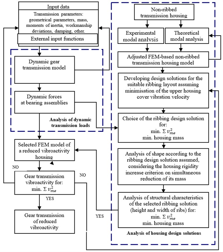
Based on results of the aforementioned bench tests and simulation studies, a method of computer-aided selection of design solutions was proposed with regard to the ribbing of gear transmission housings of reduced vibroactivity and mass (Fig. 11). The gear transmission vibroactivity thus established, given by the value of the transmission vibroactivity measure proposed (dependence 2), assuming the input functions identified in bearing assemblies and following the choice of the FEM housing model, makes it possible to assess vibroactivity of gear transmissions. Making a legitimate choice of structural characteristics of the transmission as well as of the appropriate design solution for the ribbing for its housing, reinforced by minimisation of external loads in the power transmission system, one is able to make a choice of a design solution in order to develop a gear transmission of reduced vibroactivity and mass.
Fig. 10Values of vibroactivity measure vme2 depending on the hz/gp value for the assumed values of bz/gp
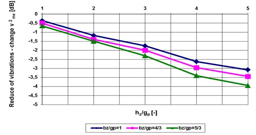
a) Housing C_1
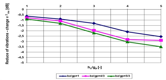
b) Housing F_1
4. Conclusions
The results acquired from simulation and experimental studies imply the legitimacy of application of the method proposed, comprising computer-aided selection of design parameters of ribbing for gear transmission housings of reduced vibroactivity and mass (Fig. 11). The fact of using original dynamic models and housings in the studies addressed in the paper makes it possible to choose an appropriate design solution for a gear transmission of reduced vibroactivity and mass.
Using input data which determine the transmission parameters and external input functions, one can make an appropriate selection of geometrical and technological properties of gears and bearings. Analysing dynamic transmission loads by means of an identified and developed dynamic gear transmission model provides grounds for choosing the optimum solution ensuring minimisation of dynamic loads at the meshing and bearing assemblies of shafts. For purposes of the analysis of the housing ribbing design solutions as well as the chosen FEM model of a reduced vibroactivity housing, the dynamic forces determined to be acting in bearing assemblies were assumed as the input functions.
While performing the analysis of the housing design solutions, it was proposed that both experimental and theoretical modal analyses of a non-ribbed housing should be undertaken. Using adjusted modal housing models made it possible to establish the correct layout of the additional transmission ribbing. The grounds for the vibroactivity assessment of the design solutions developed for the housings in question are provided by the analysis of distribution of normal vibration velocities in computational nodes of their FEM models. The fact of assuming the identified dynamic forces acting in bearing assemblies as the input functions for purposes of the analysis of the housing ribbing design solutions allows for making a choice of the ribbing layout solution, bearing in mind the condition of the housing vibroactivity minimisation simultaneously limiting the increase of its mass. By completing an analysis of the ribbing shape according to the chosen solution, one is able to modify the ribbing with regard to the housing rigidity criterion, additionally reducing its mass. By way of analysis of the housing ribbing structural characteristics (i.e. height and width), accounting for the prerequisite of the housing vibroactivity minimisation and simultaneous limitation of the increase of its mass, one can choose the FEM housing model with actually reduced vibroactivity.
Fig. 11Computer-aided engineering method proposed for designing of gear transmission housings of reduced vibroactivity and mass
References
-
Engel Z., Cempel C. Vibroacoustics and its place in science. Bulletin of the Polish Academy of Sciences, Vol. 49, Issue 2, 2001, p. 185-198.
-
Wieczorek A. Methods of noise reduction gears. The Work Safety, 11, 2008, p. 9-11, (in Polish).
-
Szaraniec A. M. The structural and technological analysis of housings of machinery and equipment. Archive Technology and Automation, Vol. 27, Issue 2, 2007, p. 121-129, (in Polish).
-
Kato M., Inoue K., Shibata K. Evaluation of Sound Power Radiated by a Gearbox. International Gearing Conference, Newcastle, 1994.
-
Wilk A., Madej H., Łazarz B. The Vibroactivity of Gear Transmissions – the Impact of Design Features and Wear Elements on Vibroactivity Drive Systems with Gear Transmissions. Institute for Sustainable Technologies, Katowice-Radom, 2009, (in Polish).
-
Shen A., Randall R. B. Optimal rib stiffening for noise reduction of constant speed gearboxes. 15th International Congress on Sound and Vibration, Korea, Daejeon, 2008.
-
Ewins D. J. Modal Testing: Theory and Practice. Research Studies Press Ltd., England, 2001.
-
Allemang R. J., Brown D. L. A correlation coefficient for modal vector analysis. Proceedings of the 1st International Modal Analysis Conference, Orlando FL, 1982, p. 110-116.
-
Folęga P., Burdzik R., Konieczny Ł., Wieczorek A. Influence of housing ribbing modification on frequencies and shapes of vibration. Journal of Measurements in Engineering, Vol. 1, Issue 3, 2013, p. 159-164.
-
Folęga P. Effect of selected structural factors on vibroactivity of gear transmissions. Measurement Automation and Monitoring, Vol. 56, Issue 6, 2010, p. 602-605, (in Polish).
-
Folęga P., Burdzik R. Contact-free measurements of vibroactivity of machine housings. Testing and Teaching Apparatus, Vol. 15, Issue 1, 2010, p. 15-21, (in Polish).
-
Łazarz B., Peruń G. The Dynamic Model of a Laboratory Station with Gear Transmissions. Scientific Booklets of the Silesian University of Technology – Transport Series, Gliwice, Vol. 63, 2006, (in Polish).
-
Łazarz B., Peruń G. The Identification of Dynamic Model of a Laboratory Station with Gear Transmissions. Scientific Booklets of the Silesian University of Technology – Transport Series, Gliwice, Vol. 61, 2007, (in Polish).
-
Bensoe M. P., Sigmund O. Topology Optimization. Theory, Methods, and Applications. Springer-Verlag, Berlin-Heidelberg, 2004.
-
Fredricson H. Structural topology optimization: an application review. International Journal Vehicle Design, Vol. 37, Issue 1, 2005, p. 67-80.
Cited by
About this article

