Abstract
This paper presents a novel fluid damping based hybrid drive multi-degrees-of-freedom permanent magnet motor. The structure and working principle of the motor is introduced. The torque features are analyzed using both finite element method and analytical method. Based on the thermal safety and thermal stability in the practical design of this motor, the thermal characteristics with heat sources are calculated and simulated. By using FEA software to model the heating status when the motor works under rated operation and high overload current conditions, the temperature contours within the motor structure can be obtained. The fluid and modal analysis are also conducted with numerical simulation. The research results validate the reasonable structure design of this motor and can be the reference of structure optimization and performance improvement indicators for this kind of motors.
1. Introduction
Compared with the traditional multi-degree-of-freedom drive devices, the permanent magnet multi-degree-of-freedom (m-DOF) motors have many advantages such as the compact space, high system efficiency, high magnetic energy product etc. In recent years, great progresses have been made on the research of the m-DOF permanent magnet motor, but the research on the liquid suspension of m-DOF motor is relatively few. In 2002, L. S. Stephens put forward a novel self-suspension motor, which takes self-bearing technology to replace the traditional bearing and uses the Lorenz force to produce a levitation force and torque. Then the analytic expression was derived to calculate the electromagnetic force and torque by magnetic flux model, and the electromagnetic force-rotor position-current curve were obtained, which was applied to the motor prototype for verification [1]. Over the next few years, in China, the suspension technology is applied to switched reluctance motor (SRM) by Li Zeng and so on, where the structure of the motor were designed and analyzed from two aspects of mechanical and electromagnetic; 3D motor air-gap magnetic density, torque and electromagnetic force analysis and finite element model was established; a motor control system model based on fuzzy control algorithm to decouple solve motor electromagnetic force and torque was established [2, 3]. In 2010, a new type of non-bearing switched reluctance motor was proposed on the basis of the spherical switched reluctance motor in Nanjing University of Aeronautics and Astronautics, which uses a double winding structure to realize the levitation control [4]. Under the guidance of the relevant theory, non-bearing m-DOF slice motors, Halbach array non-bearing permanent magnet motors have been developed, which play a role to promote the application of fluid suspension technology in m-DOF permanent magnet motor. The liquid suspension m-DOF permanent magnet motor uses the magnetic levitation control technology to realize the motor rotor’s self-levitation. This design reduces the common bearing friction, decreases the rate of mechanical vibration, torque ripple and magnetic deterioration caused by the eccentricity of the rotor, and improves the efficiency, prolongs the service life of the motor, which has a great reference value in the design and implementation of this kind of m-DOF motors.
In the field of aerospace aircraft, radar, mechanical joints etc., this kind of motor has broad application prospects. However, in the movement process of m-DOF motors, the frictional resistance of mechanism between various components reduces the positioning precision of the rotor, also generates the heat, reducing the work efficiency and even shortening the life of the motor and so on. Therefore, for the operation of the motor, the introduction of the liquid suspension to achieve the motor self-suspension control can avoid the influence of bearing factors effectively. During its operation process, the motor’s temperature rise problem affects the security, service life and reliability directly. For PM motors, the high temperature causes the irreversible demagnetization of the permanent magnets as well as the damage of the internal sensor, which should be paid more attention. Currently, the 3D modeling and simulation method is widely used with the analysis of the permanent magnet motor's heating conditions. The low accuracy and the limitations on the analysis of the distribution of whole motor’s temperature should be properly treated in this method. In this paper, the model structure and working principle of the motor are introduced initially, and then the analysis of the torque characteristics with the fluid damping mode of the motor is carried out; finally, the thermal safety and working stability are calculated and demonstrated. In order to derive the thermal safety and operation stability of this new PM 3-DOF motor, the 3D simulation analysis is made based on the cases under rated operation and high current overload status of the motor. This work focuses on the analysis of rising temperature under different operating currents of this PM motor. The temperature contours clearly show the temperature rising of each part of the motor and then verify the rationality of the structure design of the motor and the heat conditions during the operation process.
Currently, the calculation method in motor temperature field includes the simplified formula, the equivalent thermal circuit method, the equivalent thermal network method, the finite element method and the finite difference method etc. [5]. The finite element method can change the element unit size of the network based on the needs of research due to its flexibility [6, 7]. For complex models, different boundary conditions and material properties can be flexibly operated, which is intuitive and easy to analyze the simulation results. This is the most common thermal analysis method for motors. With the rapid development of computer technology, there are many software for thermal analysis based on the finite element numerical simulation, such as the finite element simulation software ANSYS WORKBENCH for the fluid, electric field, magnetic field and temperature field simulation analysis applications. In ANSYS WORKBENCH thermal analysis module, the heat balance equation is established based on the first law of thermodynamics, and the nodes are calculated by the finite element method and temperature, but the heat conduction, convection and radiation heat transfer mode is analyzed [8-10]. Combined with the features of the motor and the advantages of the finite element numerical analysis, this research adopts ANSYS WORKBENCH to the steady and transient state thermal analysis module to the PM motor thermal simulation.
2. Structure, working principle and torque characteristics of the motor
2.1. Structure of the motor
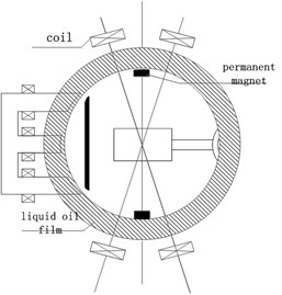
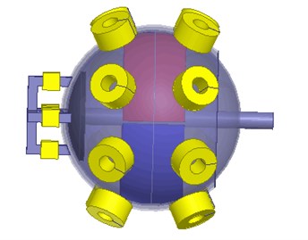
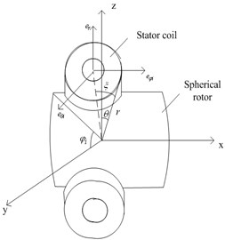
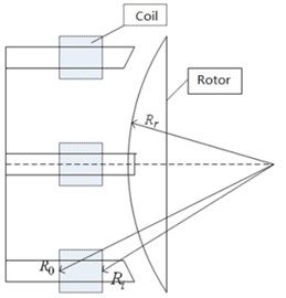
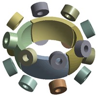
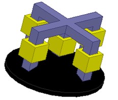
The m-DOF hybrid drive motor mainly includes the rotor, stator coil, damping fluid and rotor shell. The rotor is hollow, whose inner surface is inlaid with permanent magnets. The permanent magnet of the vertical position can complete a large-scale movement, and the permanent magnet positioned at the end can realize an accurate fine tuning. The periphery of the rotor is surrounded by cylindrical stator coil. The gap between the stator and rotor are sealed with liquid to adjust the damping of the rotor movement. According to the structure which is mentioned above, the assumption of a modeling process can be shown as following: 1) ignore the magnetic circuit saturation; 2) during the research of magnetic field, ignore the eddy current effects caused by magnetic field changes; 3) the magnetic field created by the energized coils only has effects on the rotor magnetic poles which is nearby the coils. The magnetic field has less effects on rotor magnetic poles which is not adjacent to the coils so that the magnetic field can be ignored; 4) the magnetic material is isotropic medium. The structure of the motor is shown in Fig. 1, detailed parameters are listed in Table 1.
Table 1Parameters of the motor
Name | Value |
The stator outer diameter of the spherical shell / mm | 53 |
Large range of movement of the permanent magnet outer diameter / mm | 48 |
Large-scale movement of permanent magnet inner diameter / mm | 38 |
Spherical outside diameter rotor / mm | 50 |
Permanent magnet gap at all levels / mm | 3 |
Fig. 1Motor structure
2.2. Working principle of the motor
The N and S-poles in the PM rotor are distributed alternately. When the vertical or the horizontal stator coils are energized, there is an interaction between magnetic field created by the stator coils and vertical or horizontal permanent magnets, then it creates tangential force, which will cause an eccentric motion of the rotor. However, the tangential force of the contrary direction is used to complete the deflection of the motor.
When the rotor occurs deflection, the position-detection device located in the hollow part of the rotor will make a real-time detection to the position of the rotor and then make a comparison with the expected value. By tracking and controlling the currents of the stator coils in different horizontal positions, the rotor can achieve a large-scale deflection.
When energized with particular direction and amplitude currents, the stator coils make the air gap magnetic circuit change. Then, the deflected motion occurs with rotor slightly. By changing the direction of currents in different coils, the rotor can achieve fine-tuning motion. The hybrid operation mode of the motor can be realized by combining the large-scale deflection motion and fine tuning.
2.3. Motor torque characteristics
The torque characteristics are essential performance in multi-DOF hybrid drive motor with permanent magnet. The quality of torque characteristics is closely related with the structure of rotor and stator, the current of winding and the size of the air gap. The torque of the motor can be divided into large-scale motion torque and small-scale fine tuning torque, which compose the hybrid and meet the demands of accuracy. In the simulation, a 100 ampere-turns magnetomotive force is applied to the motor to implement the radial magnetization, then the torque characteristics can be achieved according to the motor energized strategy [11-13].
2.3.1. The large-scale motion torque of the motor
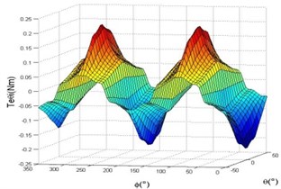
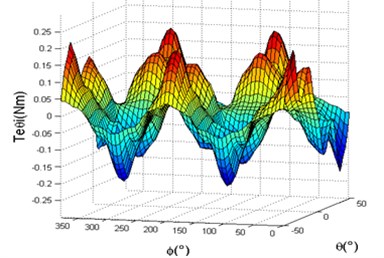
After energizing a group of stator coils with same polarity, the rotor rotates around the axis, calculates the torque every 20°, the curve of the torque with a large-scale motion is shown in Fig. 2. It can be seen from the figure that the torque is changing periodically when the rotor completes a periodic motion, which has two positive and two negative maximum values. Periodic distribution of torque is in accord with the permanent magnet field, and the maximum torque is 0.19 Nm. Combined with the energized policy of the motor, the motor can achieve a large-scale deflection motion. According to the principle of motor deflection motion, and considering the rotation of the motor and the large-scale deflection motion, the 3D curve of the torque characteristics with large-scale motion is shown in Fig. 3.
Fig. 2Torque characteristic of the rotation torque characteristics
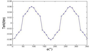
Fig. 3The torque characteristics of large-scale motion
2.3.2. Fine-tuning drive torque
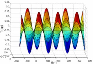
In the case of exerting 80 ampere-turns magnetomotive force to the controlled coils of the fine-tuning movement and calculating the torque every 2°, energizing the coils positioned at the end, the curve of torque can be seen from Fig. 4. The torque is 0.07 Nm when the motor is in the initial position. While energizing different coils as the rotor rotates to 9°, the torque becomes stronger; and when the rotor rotates to 15°, the torque returns to 0.07 Nm. Fig. 4 is the 3D diagram of the motor torque characteristics, which is combined with the motor rotation movement. It is easy to have a higher precision by applying the hybrid drive model which is combined with fine-tuning motion and the large-scale motion of the motor.
Fig. 43D torque characteristics diagram
2.4. Analytical modeling of torque characteristics
Currently, according to different structures and principles of PM motors, the torque calculation method can be divided into: a) Lorentz force law; b) Virtual displacement method; c) Maxwell tensor method. This section will choose Lorentz force method to model and analyze the torque of the motor.
2.4.1. Torque calculation principles of the Lorentz force law
The torque principle of 3-DOF hybrid drive motor with permanent magnet is that the electromagnetic force is created by the interaction between magnetic field of the stator generated by the coil and the magnetic field generated by rotor permanent magnet, and the force can thus be produced to drive the motor. The size and direction of the electromagnetic force of the stator coils are relate to the position of the rotor magnetic poles and the currents of the stator coils, that is:
where is the relative position of the stator energized coils and the rotor magnetic poles in a spherical coordinate system, is the currents of the stator coils. The vector of along the tangential direction of the rotor spherical surface can create a electromagnetic torque, which can complete the 3-DOF motion. The vector of along the radial direction can create the suspension force. The torque generated by a single energized coil is:
The rotor permanent magnet of m-DOF hybrid drive PM motor interacts with the stator coils which are energized. Under the condition of neglecting the saturation of magnetic circuit, the total electromagnetic torque can be seen as a linear superposition of the vector which is generated by the each coil. The total torque can be expressed as follows:
where is the number of energized coils; is current value of the stator coil . Therefore, establishing torque model can be divided into two processes, that is, torque modeling of a single coil and torque modeling of multiple coils.
The torque calculation principles of the Lorentz force law can be expressed as follows:
where is the current applied to the current-carrying, is the length differential of current-carrying. If each current element has the same direction when applied the electromagnetic force, the vector sum of the electromagnetic force can be converted into algebraic sum. The further simplification is:
where is the angle between the current-carrying conductor and the direction of magnetic field.
2.4.2. Lorentz force law torque model
2.4.2.1. Torque model of single coil
The single coil structure parameters, air gap magnetic field flux density and distribution are closely related each other. Taking into account the special structure of the stator and rotor as well as the distribution of air gap magnetic field, the torque modeling is operated in a spherical coordinates. The specific parameters are shown in Fig. 5.
is the outer diameter of the stator coil, is the inner diameter of the stator coil. By using Lorentz force law, the electromagnetic force created by the differential element of each coil is:
The torque created by differential element is:
Only the tangential electromagnetic force generated by the air gap magnetic flux density along can drive the motor, so it is needed to solve the radial vector of the air gap magnetic flux density. Integrating Eq. (7), the torque of a single coil can be calculated as follows:
This hybrid drive PM motor can achieve m-DOF deflection motion around the -axis as well as the -axis, -axis. Therefore, the torque model can be divided into the rotation torque model and deflection torque model. The conversion between spherical coordinates and Cartesian coordinate system is shown as follows:
In spherical coordinates, and are the local Cartesian coordinate system of the axis, as is shown in Fig. 6.
Fig. 5Stator coil
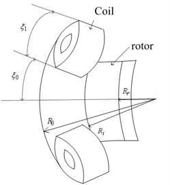
Fig. 6Spherical local Cartesian coordinate system
As can be seen, each unit under the spherical coordinates can be transformed into units under the Cartesian coordinate system. The expressions are shown as follows:
Resolve the differential element along the local rectangular coordinates:
where:
From the above expressions, it can be derived that the electromagnetic torque of the deflection movement around the , , and axis under the rectangular coordinates, which is shown as:
From the obtained torque model created by a single coil, it is obviously that the size of the torque is related to the distribution of the air-gap magnetic field, structure parameters of the stator coil, and the relative position of the stator and rotor.
2.4.2.2. Torque model of multiple coils
In the case of ignoring the saturation of magnetic circuit, the total torque can be seen as a linear superposition of the torque generated by single coils. When the number of the energized stator coil is , the expression of the resultant torque is shown as follows:
where is the amplitude of the radial vector of the air-gap magnetic field:
where is the density matrix of current surface flowing through the coil.
Similarly, the rear coils also use the method that is mentioned above. The specific rear coils are shown in Fig.7.
Fig. 7The rear fine motion control coils
2.4.2.3. Torque calculation results by analytical method
It is necessary to solve the electromagnetic torque which is created by single coil models, because this torque component is an essential prerequisite of the total torque. The torque function is related to and . The 3D spatial distribution of the torque is shown in Fig. 8 and 9.
Fig. 8Rotation torque characteristics diagram with analytical method
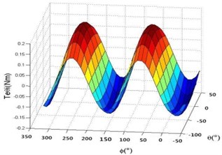
Fig. 9Deflection torque characteristics diagram with analytical method
2.4.2.4. Difference between two approaches
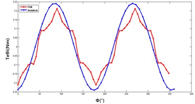
As shown in Fig. 3 and 8, the rotation torque around the -axis motor within a period of has four extreme points, two peaks and two troughs. As shown in Figs. 4 and 9, the two figures are both have one extreme point, it is obvious that the torque characteristics of deflection movement are similar to the fine-tuning motion. Through the above analysis, it is concluded that the motor can achieve a 3-DOF movement by controlling the coils with different positions.
However, there are some difference between these two approaches. The analytical modeling of the motor rotation torque is implemented by solving Laplace’s equation in spherical coordinates, at the same time, using MATLAB simulation software, the single coil produced torque and the multiple coils produced torque of the motor are modeled, also obtaining the relationship between the torque of the motor rotation and the rotation angle of the spherical coordinate system. The analytical method has smaller computation workload, and it can directly obtain the relationships between the performance of the motor and its structural parameters. The end effect is ignored in the calculation process, and the boundary conditions are simplified, therefore, it is difficult to get the effect of magnetic flux leakage on the electromagnetic torque of the motor, as shown in Fig. 10.
Fig. 10Comparison of rotation torque of 2 methods
3. Motor thermal analysis basic theory of temperature field
3.1. Heat transfer for the motor
Thermal conduction is ubiquitous in nature, the three forms of the heat conduction in the motor is shown as follows: thermal conduction, thermal convection and thermal radiation [14-17].
1) Thermal conduction is the process of energy transfer which is from high-energy particles to low-energy particles. Fourier theorem illuminates that the heat on the isotherm surface in unit time is related to the temperature gradient (space temperature change rate) on the isotherm surface in the normal direction, i.e.:
where is the heat flux intensity, is the thermal conductivity, is the temperature gradient, the minus sign describes the direction. The temperature gradient is shown as follows:
where , , is the unit vector along the , , axis.
2)Thermal convection consist of two forms of energy exchange, one is the microcosmic energy exchange which is created by molecular motion; the other is macroscopic energy exchange that is created by energy exchange. There are many factors that affect the energy exchange, including the shape of the object’s surface and the thermal characteristics of heat transfer medium, etc. By summarizing the various situation of heat convection, the thermal density expressions is as follows:
where is the convective coefficient of the heat transfer, is the surface temperature, is the medium temperature of heat transfer.
3) Thermal radiation is the energy that is released by the object under a certain temperature. Different from the other two types of heat transfer, thermal radiation dose not require medium. According to the Stephen-Boltzmann law, the transfer pattern of heat radiation can be expressed as:
where is the absolute temperature of the surface, is a constant of the Stephen-Boltzmann, which is also known as black-body radiation constant, its value is usually 5.67×10⁻⁸ W/(m2·K-4).
If the interaction between a little surface and a large surface that completely surrounds it produces the net radiation heat transfer in the actual situation, the heat flow of the net radiation can be shown as:
where is the area of the little surface, is the exterior blackness (emissivity), its value is related to the types of objects and the surface state, which is usually less than 1. is the temperature of the large surface.
3.2. Mathematical model of temperature field
In this paper, the thermal analysis module of finite element simulation software ANSYS WORKBENCH is used to analyze the steady state and transient state of the new type permanent magnet motor. Compared with the steady-state simulation, transient analysis get the temperature changes with time, but the loading of heat load is an ideal scheme in the simulation. Therefore, the transient analysis method applied to the calculation of the motor heating is not mature for the application.
The method used to solve thermal conduction equation is the temperature field method which is based on the numerical calculation. According the way of heat transfer, the thermal conduction equation is:
where is the coefficient of the derivative along different direction, is the density, is the specific heat capacity, is the temperature, is the heat production rate of unit volume.
The research method of the temperature field means a transform from the whole to the part, from the macro to the micro. In the steady state temperature field, the heat conduction equation is . The common boundary conditions can be divided into the following three categories [18, 19].
1) The first kinds of boundary condition (The temperature boundary condition):
2) The second kinds of boundary conditions (The heat flux boundary condition):
3) The third kinds of boundary condition (The heat transfer boundary condition):
where is the given temperature on the boundary surface , is the heat flow on the boundary surface , is the thermal conductivity, is the coefficient of the heat transfer on the boundary surface.
3.3. The basic idea of the finite element thermal analysis
Finite element software can handle the three kinds of heat transfer modes mentioned above, and it also can analyze the phase change, internal heat source, contacted thermal resistance and other issues. Generally, the basic idea of the finite element method comprise the following [20, 21]:
1) Put forward a hypothetical. Make the continuous system divide into finite elements, then let each element act as a node in the finite element system;
2) Build the interaction between unknown and nodes of each element. In the finite element systems, each node has its own coordinates and the corresponding DOF. Besides, different nodes have different DOFs;
3) Divide the elements according to certain conditions, then introduce the boundary condition and construct equations to solve the unknown. The essence of the finite element thermal analysis is to divide the continuous system with infinite DOFs into units with finite DOFs, so that it can be solved easily by numerical method by idealized models.
3.4. Motor internal heating source
As a kind of complex energy conversion device, motors generate all kinds of losses during movement. Most of these losses are transformed into the form of heat, thus make the temperature increase. So, it is very important to ascertain and calculate the heat source in the process of calculating the motor’s temperature rise. Generally, factors affecting the temperature of the motor include winding loss (copper loss), core loss and mechanical loss, etc. [22, 23].
1) Winding loss.
The object of the research is the PM motor whose rotor has no coils, so mainly the stator windings generate the copper loss. The value of the copper loss with current is:
where is coefficient of wire resistance when the temperature is ; is the temperature; is the temperature coefficient; is the current density.
2) Core loss.
For the PM motors, the iron loss includes eddy current loss and magnetic hysteresis loss, which is created by the alternating magnetic field running through the stator core or PM rotor. In this paper, the rotor of the motor is the permanent magnet, which is not configured with additional power supply. However, there are also some harmonic from air gap magnetic field during the operation, it also generates the eddy current loss. Compared with the stator loss, the rotor iron loss is lower, so it can be ignored in the analysis. Generally, the first step is carry out the magnetic field analysis and experiment because the calculation of the iron loss is more complex, then apply the empirical formula to calculate the iron loss, the empirical formula is as:
where is the empirical coefficient; is the net usage of iron core.
3) Mechanical loss.
Mechanical loss mainly includes friction loss among the components of the motor, such as friction loss of the bearing, ventilation loss and brush friction loss, etc. Usually, the result of the calculation is always an estimate according to the empirical data or the experimental data, because it is difficult to make a accurate calculation of the mechanical loss. In this work, the mechanical loss is limited which has a less impact on the motor's temperature rise, so it can be ignored [24].
4. Motor thermal analysis model for FEA
4.1. Model building
In this paper, the 3D FEA model of thermal stability is used for calculating thermal characteristics of the three DOF PM motor. The structure of the motor is complicated with two layers. In order to observe the internal windings’ temperature rise clearly, local thermal analysis with subdivision of the motor is considered necessary. Fig. 11 shows the solid pattern of the motor and Fig. 12 shows the solid pattern of the motor after mesh setting.
Fig. 11Motor model illustration
4.2. The boundary condition
The boundary conditions of computation domain of the model are set up before the thermal analysis. In order to simplify the analysis process, there are some assumptions to the motor model: 1) ignore the thermal dissipation of the motor end components; 2) ignore the temperature effect of the motor enclosure; 3) ignore the thermal conduction between permanent magnet and the rotor shaft. Based on the above assumptions, the inner core of the permanent magnet rotor is exerted with the second kind of boundary condition, which is also called insulation boundary condition, and other model surface contacts with the outside is exerted natural convection boundary condition.
Fig. 12Model mesh diagram

4.3. Motor thermal parameters
The motor presented is an original multiple dimensional motion motor, whose rated current is 1.4 A. The main material of the motor includes silicon, copper wire, and NdFeB. Thermal parameters of the material are shown in the Table 2.
Table 2Thermal physical parameters of motor material
Material | Thermal conductivity W(m·k)-1 | Specific heat capacity J·(kg·K)-1 | Density kg·m-3 |
Silicon | 23 | 448 | 7750 |
Cooper | 400 | 386 | 8933 |
NdFeB | 10 | 350 | 8300 |
5. The results of simulation and analysis
5.1. Temperature rise with rated situation
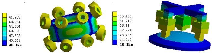
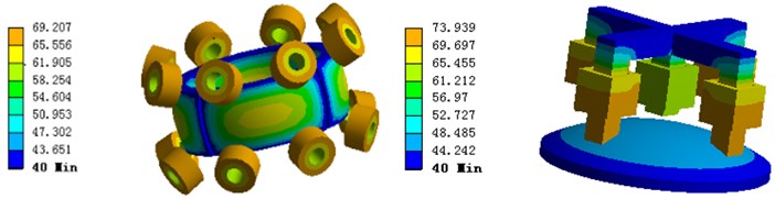
The initial temperature is set with 20 °C as the same of the environment temperature. According to natural convection, the given thermal conductivity is without a cooling device. The results for 3D contours of the motor heat distribution are shown in Fig. 13, and the local heat distribution are shown in Fig. 14.
Fig. 13Motor temperature distribution of the large range motion part model
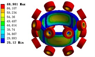
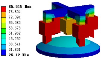
Fig. 14Motor temperature distribution of the fine tuning part model
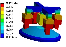
From Fig. 13 and 14, it can be seen that the highest temperature of the motor is 72 °C without a cooling device, the initial temperature increases from 20 °C to 25.1 °C. Obviously, the highest part of temperature is in stator coil, which means the copper loss plays a major role in the motor’s temperature rise. The difference between the stator and rotor’s temperature rise is that the air gap between permanent magnets and stator coil is narrow, which makes the PM rotor has a distinct temperature rise.
5.2. Temperature rise with rated situation on different materials and environment
As mentioned above, the material of the motor is composed of silicon, cooper and NdFeB. Taking into account different materials’ effects on the temperature field, the following changes of the materials of the motor are listed as Table 3.
Table 3Thermal physical parameters of motor materials
Material | Thermal conductivity W(m·k)-1 | Specific heat capacity J·(kg·K)-1 | Density kg·m-3 |
Steel | 50 | 448 | 7750 |
Cooper | 380 | 386 | 8933 |
Structural Steel | 60.5 | 3.50 | 8300 |
The settings of the ambient temperature and the initial temperature are also 20 °C, the heat transfer coefficient of the motor under the condition of natural convection heat transfer has not changed. The results for 3D contours of the motor’s large range motion part heat distribution are shown in Fig. 15, and the fine tuning part heat distribution are shown in Fig. 16.
It can be seen that different materials play very important roles for the analysis of the thermal stability of the motor, which is not only related to the highest and lowest temperature of heating, but also affects the thermal conductivity. Similarly, when the environment changes, the corresponding temperature will also changes.
Fig. 15Motor temperature distribution of the large range motion part model
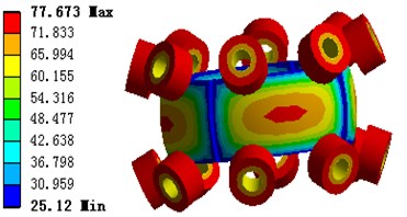
Fig. 16Motor temperature distribution of the fine tuning part model
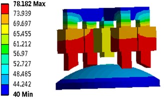
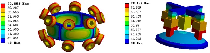
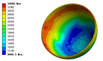
5.3. Temperature rise with overload situation
Fig. 17 and 18 show the temperature of the motor which works under 1.5 times of rated current situation without radiator, the maximum temperature is 78.1 °C, the minimum temperature is 40 °C, the temperature of the winding is higher than that of other components of the motor, the temperature of PM rotor is also in a high level. It is clear that the copper loss is the main factor of temperature rise in the case of overload operation.
Fig. 17Motor temperature distribution of the large range motion part model
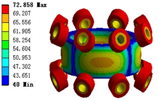
Fig. 18Motor temperature distribution of the fine tuning part model
5.4. Temperature rise analysis
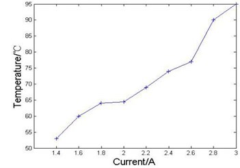
The permanent magnets with different temperature appear various magnetic properties, while over high temperature may lead to magnetic weakness or irreversible demagnetization. In order to ensure the stability and security of the motor, it is crucial to figure out the temperature changing characteristics under different working conditions. Fig. 19 shows the highest temperature rise of the motor in different working environment. It can be seen from the figure that the initial temperature is 54 °C, while, as the rated current rises from 1.4 A to 3 A, the temperature has risen to 65 °C. It indicates that with the increase of the current, the temperature rise gets worse, which actually causes some effects on the operation stability of the motor.
Fig. 19Curve of the temperature with respect to different currents
5.5. Transient state thermal analysis
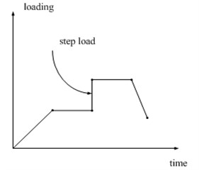
In the actual motor heating process, the material thermal conductivity and heat generation rate and so on are nonlinear variables along with temperature and time, so it is not only need to analyze motor in steady state at a given time, but also solve the transient change within a certain period of time, which can obtain the instantaneous relationship of the motor heating along with time. In this paper, the ANSYS WORKBENCH transient analysis module is used to simulate these transient problems. In the process of transient analysis with finite element method, the first step is to conduct nonlinear analysis about the iterative solving of convection coefficient and materials parameters that include heat transfer coefficient, specific heat and density. Thermal load (heat rate) of transient analysis is a nonlinear variable which is changing with time, so it is necessary to make a load - time curve, thermal load changing time characteristics with time in the ideal model, which is shown in Fig. 20. The abscissa represents time, ordinate is marked with loading, and inflection point represents a load step in the curve, where each load step can be set with corresponding load value by means of the gradient, the step or the automatic step change.
Fig. 20Time varying heat load
The basic steps of transient state thermal analysis simulation in ANSYS WORKBENCH is similar with steady state analysis, which needs to make the heat generation rate variable change with time. In order to save the time and the memory, the transient simulation time is set with 20 seconds, the number of simulation step is 20 steps, the calculation time is 1 hours 15 minutes 12 seconds. According to the heating condition of the motor’s winding, the time variable heat load is set as the step change forms. From the simulation, the temperature rise of the motor at different times are given in Fig. 21.
The Fig. 21 shows that motor heating is changing with time. In the trend of overall temperature, the air-gap along the stator yoke and rotor permanent magnet spread outward from winding center (at 1 s), which make the stator yoke and rotor permanent magnet without heat source also have a certain temperature in the simulation. As the simulation time is short, there is a big difference between the stator winding temperature and environment temperature, while, the difference between the stator yoke and environment temperature is the least.
Fig. 21Motor temperature rise at different time
a) Motor temperature rise at 1 s
b) Motor temperature rise at 11 s
c) Motor temperature rise at 20 s
Fig. 22Changes of motor temperature with time
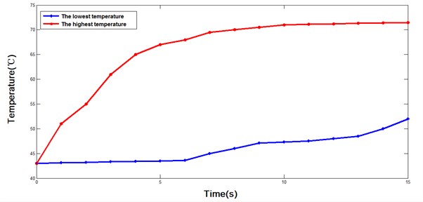
Fig. 22 shows the two-dimensional curves where the maximum temperature and minimum temperature in the motor model are changing with time. It can be seen from the figure that the maximum temperature increases significantly as the simulation time goes by. The temperature presents an upward trend at the beginning of the curve, and the stator winding temperature increases quickly, the growth rate gradually slows down with time, which is close to a smooth trend in the next 10 s. On the contrary, the motor’s lowest temperature grows slowly at the first 5 s, and the curve is approximately straight. While, the growth rate of minimum temperature is significantly accelerating after 5 s.
6. Fluid and modal analysis
The liquid oil film sealed between the stator and rotor shells of the motor plays an important role in regulating the rotor of the motor. The oil film is attached directly to the surface of stator and rotor, which has the same speed as the rotor, so the influence of rotor and stator can be ignored when establishing the simulation model of oil film. Firstly, the oil film model is created, which is imported into ANSYS FLUENT module to implement the fluid analysis. The pressure distribution of the oil film surface between stator and rotor is shown as Fig. 23.
Fig. 23Pressure distribution of liquid oil film
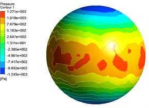
a) Pressure distribution of stator surface
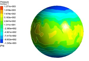
b) Pressure distribution of rotor surface
From the above figures, it can be seen the pressure of the contact surface between the oil film and the rotor is less than that between the oil film and the stator. The pressure distribution is inhomogeneous, whose maximum value is distributed in the center of the sphere model. After the fluid analysis, the model is imported into ANSYS Static-Structural module, where the force based modal analysis of the spherical rotor is carried out. The force by oil film that exerted on the stator shell can be shown in Fig. 24.
Fig. 24Pressure and deformation distribution of stator
a) Equivalent stress distribution of stator
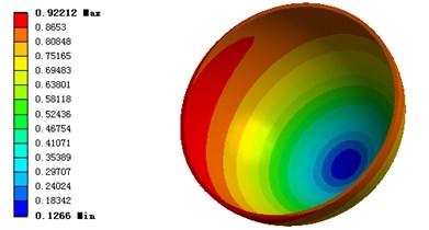
b) Total deformation of stator
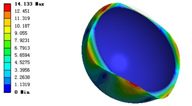
Compared with the oil film pressure distribution, the equivalent stress and the total deformation are gathered in the center of the stator. When the rotor rotates, the motor shell can be deformed under the force or vibration. The deformation of the shell is shown as Fig. 25.
It can be seen from the figure that the maximum deformation is on the edge of the model, it is also means that the maximum deformation is in the center of the motor shell, and there is a decreasing trend of the deformation from center to both sides.
Fig. 25Deformation of motor shell
7. Conclusions
In this paper, by using the finite element simulation software for a fluid damping based permanent magnet 3-DOF motor torque characteristics and heating situations are analyzed and calculated. The analytic Lorenz method and 3D finite element method are used to analyze the torque features of the motor in detail, and the results of comparative analysis verify the validity of the application of these two methods. Under the rated conditions, the heating sources of high current overload working status is mainly discussed, by establishing the calculation model of the temperature field under different loading conditions, to solve the specific calculation results. The calculation results show that, the motor in the rated working conditions within the highest temperature is 72 °C, in a safe operating temperature range. To validate the rationality of the design of the model, the stator coils are treated as the main heat source, which in turn shows that copper loss in the motor. The heating effect by the motor's iron loss is not obvious. Due to the permanent magnet rotor and the stator's iron core, the motor under the condition of large current work status may lead to the temperature rise too high on the permanent magnet rotor, which affects the stability. The fluid and modal analysis show the pressure distribution and deformation caused by the fluid and electromagnetic forces, which may lead to the material damage, vibration and motor performance variation. The results provide a basis and reference for the further design and optimization of related kinds of motors or actuators.
References
-
Stephen L. S., Dae Gon K. Force and torque characteristics for a slotless Lorentz self-bearing servomotor. IEEE Transactions on Magnetics, Vol. 38, Issue 4, 2002, p. 1764-1773.
-
Liu Jing, Zeng Li, Yang Jun, et al. Finite element method to calculate the magnetic field distribution of magnetic suspension spherical reluctance motor. Xuzhou Institute of Technology (Natural Science Edition), Vol. 25, Issue 3, 2010, p. 19-23.
-
Zhang Qiang, Zeng Li, Hu Feng Research on the control system of the magnetic suspension spherical motor. Mechanical Engineering and Automation, Vol. 30, Issue 2, 2013, p. 64-66.
-
Liao Qixin Research on the Non Bearing Permanent Magnet Thin Slice Motor. Nanjing University of Aeronautics and Astronautics, Nanjing, 2005.
-
Liu Jiao, Huang Shoudao, Cheng Benquan, et al. Analysis of temperature field in a cycling oil cooled permanent magnet synchronous motor. Micromotors, Vol. 43, Issue 5, 2010, p. 10-12.
-
Guo Youguang, Zhu Jianguo, Wu Wei Thermal analysis of soft magnetic composite motors using a hybrid model with distributed heat sources. IEEE Transactions on Magnetics, Vol. 41, Issue 6, 2005, p. 2124-2128.
-
Li Zheng, Lun Qingqing, Xing Dianhui, Gao Peifeng Analysis and implementation of a three-degrees-of-freedom deflection type PM motor. IEEE Transactions on Magnetics, Vol. 51, Issue 11, 2015, p. 1-4.
-
Li Weili, Chen Tingting, Qu Fengbo, et al. Analysis on solid motor 3-D temperature field in high voltage PMSM. Proceedings of the CSEE, Vol. 30, Issue 18, 2011, p. 55-60.
-
Wang Shuifa, Chen Dewei Analysis of two-dimensional steady temperature field of asynchronous motor based on ANSYS. Electric Drive Automation, Vol. 33, Issue 2, 2011, p. 23-26.
-
Xia Zhengze, Liu Huijuan Analysis and calculation of the stator temperature field of asynchronous traction motors. Small and Special Electrical Machines, Vol. 4, 2009, p. 22-25.
-
Xia C. L., Li H. F., Shi T. N. 3D Magnetic Field and Torque Analysis of a Novel Halbach Array Permanent-magnet Spherical Motor. IEEE Transaction on Magnetics, Vol. 44, Issue 8, 2009, p. 2016-2020.
-
Wang Q. J., Li Z., Xia K., et al. Calculation and analysis on configuration parameters and torque characteristics of a novel spherical stepper motor. Proceedings of the CSEE, Vol. 26, Issue 10, 2006, p. 158-165.
-
Stephen L. S., Dae Gon K. Force and torque characteristics for a slotless Lorentz self-bearing Servomotor. IEEE Transaction on Magnetics, Vol. 38, Issue 4, 2002, p. 1764-1773.
-
Wang J., Mitchell K., Jewell G. W., et al. Multi-degree-of-freedom spherical permanent magnet motors. IEEE International Conference on Robotics and Automation, Seoul, Korea, Vol. 2, 2001, p. 1798-1805.
-
Kwon B- Il, Kim Y.-B. Design and analysis of double excited 3-degree-of-freedom motor for robots. Journal of Electrical Engineering and Technology, Vol. 6, Issue 5, 2011, p. 618-625.
-
Kral C., Habetler T. G., Harley R. G., et al. Rotor temperature estimation of squirrel-cage induction motors by means of a combined scheme of parameter estimation and a thermal equivalent model. IEEE Transactions on Industry Applications, Vol. 40, Issue 4, 2004, p. 1049-1057.
-
Rioul M. A Thermo hydraulic modeling for the stator bars of large turbo generators: development, validation by laboratory and on site tests. IEEE Transactions on Energy Conversion, Vol. 12, Issue 1, 1997, p. 1-9.
-
Alekseev G. V. Solvability of stationary boundary control problems for heat convection equations. Siberian Mathematical Journal, Vol. 39, Issue 5, 1998, p. 27-33.
-
Grabezhnaya V. A. Heat-transfer degradation boundary in supercritical-pressure flow. Atomic Energy, Vol. 101, Issue 4, 2006, p. 13-17.
-
Qu Fengbo, Li Zhipeng, Cheng Shukuang, et al. Calculation and simulation analysis on starting performance of the high-voltage line start PMSM. IEEE International Conference on Computer Application and System Modeling, 2010, p. 198-202.
-
Ma Jie, Yu Qizhi FEM calculation rotor losses in PM synchronous motor. Explosion-proof Electric Machine, Vol. 6, 2003, p. 8-10.
-
Ding Wen, Zhou Huijun, Yu Zhenmin Analysis of temperature field for switched reluctance motor based on ANSYS. Micromotors, Vol. 38, Issue 5, 2005, p. 13-15.
-
Junggi L., Kwanghee N., Seoho C. Loss minimizing control of PMSM with the use of polynomial approximations. IEEE Transactions on Power Electronics, Vol. 24, Issue 4, 2009, p. 1071-1082.
-
Wen Zhiwei, Gu Guobiao Calculation of rotor temperature field for solid pole synchronous. Large Electric Machine and Hydraulic Turbine, Vol. 2, 2005, p. 1-5.
About this article

This work is supported by the National Natural Science Foundation of China (No. 51577048, 51637001, 51107031), the Natural Science Foundation of Hebei Province of China (No. E2014208134), the Overseas Students Science and Technology Activities Funding Project of Hebei Province (No. C2015003044), the Hebei Industrial Technology Research Institute of Additive Manufacturing (Hebei University of Science and Technology) open projects funding, the National Engineering Laboratory of Energy-saving Motor and Control Technique, Anhui University (No. KFKT201601).
Zheng Li is responsible for the overall design of electromagnetic and fluid systems. Wei Nie is responsible for the modeling and calculation of fluid systems. Ruodong Zhi is responsible for the modeling and calculation of electromagnetic systems. Zengtao Xue is responsible for the heat analysis and calculation of this motor. Qunjing Wang is responsible for the torque modeling and optimization of the model of this motor.
