Abstract
An impulse-based reciprocal method is proposed for measuring the transfer functions of underwater structure. This method uses an impulse sound source, and the volume velocity of source is derived from the detected sound pressure. The influences of the reverberant sound field on the detected sound pressure are eliminated by an operation with time gates. Numerical simulation verifies that this impulses-based reciprocal measurement can obtain results with accuracy similar to the traditional reciprocal measurement method using electromagnetic source. Because much less time is required in the impulse-based measurement, the time efficiency is boosted. This method is also validated in a lake experiment, and the experimental result shows that the influences of the reverberant field on the derived volume velocity are eliminated.
1. Introduction
Measurement of structural transfer functions is important to real-time prediction of the noise radiated by structures. The transfer functions of complex structures, such as drilling platform and ship, are mostly measured in situ. In some cases, narrow measurement space and friable structures do not allow direct-actuation measurement of structural transfer functions.
In such situations, the principle of reciprocity provides a new means of measuring structural transfer function, by switching the actuating points and measuring points. Reciprocal measurement techniques are now applied in many fields. Wolde studied the sufficient conditions of reciprocal relation, and applied the principle of reciprocity in underwater transfer function measurement [1]. Lyamshev expanded the scope of application, and examined the validity of reciprocity with flow and nonlinearity [2]. Fahy reviewed researches on the reciprocity principle and its applications in noise control [3]. Musha used the reciprocity principle to determine the dominant self-noise sources of sonar [4]; Mencik studied the blocked pressure with the reciprocity principle [5]; and Godin combined the reciprocity principle with the waveguide theory to calculate the amplitudes of acoustic normal modes [6].
In many cases, the volume velocity of underwater sound source is required to determine the transfer functions based on the reciprocity principle. However, the actual testing environment is usually a reverberant sound field, which may introduce errors in the measurement of sound pressure radiated by the source, thus affecting the derived transfer functions and volume velocity. This type of errors has been paid less attention so far.
The influence of the reverberant sound fields can be broken into the homogeneity of acoustic field and the overshoot of sound energy density. The traditional approach is to average the sound pressure data collected by numerous hydrophones, for the eliminating of the inhomogeneous sound field influence; and to derive the average sound-absorption coefficient of the filed, for the correcting of the sound energy density [7, 8]. Since the difficulties of placing numerous hydrophones in waters, in many real tests, especially on seas, the reciprocal measurement is hard to be taken.
This paper proposes a reciprocal measurement method using impulse sound source, which in combination with a “time-gate” operation. Only with one hydrophone, the direct signal can be obtained, and the influences of the reverberant field are eliminated. It saves the measurement time and reduces the test difficulty greatly. In this paper, firstly, the theory of this method is introduced. Secondly, this method is verified by numerical simulation and then validated by the result of a lake experiment. Lastly, the strengths and weaknesses of this method are discussed.
2. Theory and numerical verification of the proposed method
2.1. Reciprocity principle
In the transmission of structural vibration and radiated noise, reciprocity is defined through two cases in which the environment is kept to be completely the same. In the first case, an actuating force () acting at point 1 on an underwater structural object generates sound pressure () at point 2 in the far field; in the second case, a volume velocity source () located at point 2 in the far field induces vibration velocity () at point 1 on the structure. The reciprocal relation states that the ratio of the far-field pressure () over the actuating force () in the first case equals the ratio of the vibration velocity () over the volume velocity of source () in the second case, i.e.:
The pressure and velocity response in Eq. (1) can be measured directly, but the volume velocity is normally obtained indirectly using the formula shown in Eq. (2):
where and are the volume velocity of source at circular frequency and the sound pressure at distance from the center of the source, and is the density of the medium.
The actuating forces acting on a structure are usually obtained with the pseudo-force technique [9, 10]. Firstly, select some points on the structure for pseudo-force reconstruction and some points near the structure to measure the pseudo-force responses. Next, an admittance matrix is obtained by measuring the acceleration response at the second set of points for given excitation (for example, using a force hammer) at each point in the first set:
where is the actuating-force matrix at the pseudo-force reconstruction points, and is the response-acceleration matrix at the pseudo-force response points. Although the admittance matrix varies with the immersion state of the structure, it can still be regarded as constant in case of small changes of the depth of immersion.
If the structure is a machine in operation, the pseudo-forces can be obtained on-line, based on the acceleration matrix at the pseudo-force response points:
where is the generalized inverse of the admittance matrix. In many cases, the regularization method is introduced to solve ill-conditioned .
For structural forces at the actuating points and the radiated noise at the response points, the direct transfer-function matrix can be expressed as:
The reciprocal transfer-function matrix can be expressed as:
The direct transfer function is equal to the transpose of the reciprocal transfer function:
Substituting Eq. (4-6) into Eq. (7) yields:
where , and are obtained beforehand. The sound pressure radiated by the structure can be derived from Eq. (8) and the acceleration response measured around the structure.
2.2. Impulse source and reverberation
If the outer sound source is an impulse sound source, in free sound fields, the sound pressure around the sound source in the time domain is an impulse signal:
where is the amplitude of the impulse signal, and is the time that it takes for the impulse to arrive at the measuring point. However, for sound source in a reverberant field, the reflected signals and scattered signals are superposed on the signal directly coming from the sound source. An earlier study showed that the influences of reverberation on and in Eq. (1) counteracted against each other [11], so only the influences on need to be considered:
where , and are the amplitudes of the reflected and scattered signals, and , and are the transmission time of these signals.
Eq. (10) can also be written as:
Since the reflected signals and the scattered signals have longer paths of propagation than the direct signal, . For the convenience of discussion, it is defined that . The minimum time gap between the direct signal and the early reflect signal is:
Then a time gate is defined: [12], and is applied in sound recording, i.e. only the signals in the time gate is recorded. Consequently, the signals beyond are rejected, and the influences of the reverberant field are eliminated.
Proper length of duration is required for this time gate. If the duration is too short, the signals directly coming from the source may not have enough energy in the recorded signal; if the duration is too long, the reflected and scattered signals may also be recorded [13]. In this paper, the time gate depends on the evaluated delays of direct sound and early reflected sound, at the radiated noise measuring position of the underwater sound source. is defined as:
where, and are the horizontal and vertical distances between the underwater sound source and the measuring position, is the sound speed. Likewise, is defined as:
where, is the shortest distance of the underwater sound source or the measuring position to the nearest reflecting interface. So, the time gate can be expressed as: . The spectrum of the direct signal with circular frequency at the measuring point is calculated as:
After the time-gate processing, combine the sound pressures in different operatings and generate a matrix: . Substituting into Eq. (8) yields the modified reciprocal transfer functions and the modified formula for calculating the radiated sound pressure :
2.3. Error and application condition
The reciprocity principle is the theory basic of the proposed method. So the sufficient conditions of the reciprocal validity should be satisfied in the test environments: linear, passive, bilateral and stable [14]. Besides these, there is an additional condition for the proposed method: the duration of the impulse signal is shorter than the length of the time gate .
In real engineering test, the ideal impulse is not exist. Eq. (11) can be rewritten as:
where, the amplitudes in the impulse duration are expressed with the functions:
where, is the duration of the direct signal, , ,… is the duration of the reflected signals and the scattered signals. If , part of the energy of the direct impulse signal will be out of the time gate . Based on Eq. (13) and (14), this condition can be rewritten as:
The impulse duration is a parameter depended on the capability of the underwater sound source. When the real impulse signal is similar to the ideal impulse signal, Eq. (20) is easy to be satisfied; likewise, when the distance of the nearest reflecting interface is larger, Eq. (20) is also easier to be satisfied. If the condition of Eq. (20) cannot be satisfied, the evaluated results of the direct-impulse-signals energy will be less than real, the evaluated sound source volume velocities will be undershoot, and the evaluated transfer functions of the radiated noise will be overshoot.
2.4. Numerical verification
Numerical simulation of the proposed reciprocal measurement in a lake is implemented to verify the theory introduced above. The depth of the lake is 8 meters and an impulse underwater source is located at 1 meter from the water surface. The underwater structure is a cylindrical shell model. The hydrophones, which used to measure the radiated sound pressure of the impulse underwater source, all locate 1 m away from the source. The sound speed in water is defined as 1420 m/s.
Fig. 1The sketch of the numerical simulation model
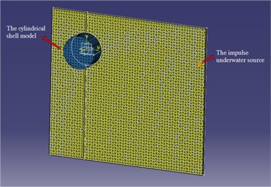
Fig. 2The sound pressure around the source (in free field)
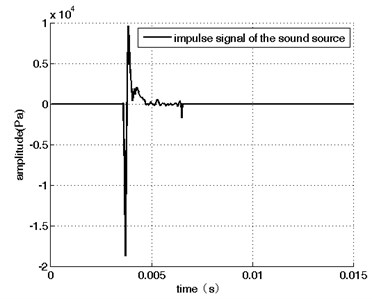
Fig. 3The sound pressure around the source (In the simulation environment). The time gate is between the dashed lines
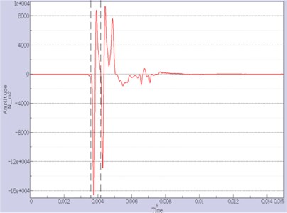
a) 0.7 m away from the water surface
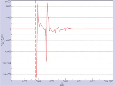
b) 1.4 m away from the water surface
In the simulation, the impulse duration is about 1 ms and it occurs at about 2.9 ms. If the simulation environment is a free field, the signals received by different hydrophones will be all the same. Fig. 2 shows the sound pressure signal around the source in this case. Most energy is concentrated between 3.6 ms and 4.8 ms.
For the reverberant field of the numerical simulation, the sound pressure signals around the source are relative to the locations. There are two different locations: (1) the hydrophone locates 0.7 m away from the water surface; (2) the hydrophone locates 1.4 m away from the water surface. According to Eq. (13) and (14), in the first case, the time gate is [3.6, 4.1] ms; and in the second case, the time gate is [3.6, 5.0] ms.
Obviously, in the first case, the hydrophone is too close to the water surface, and a part of the direct signal is out of the time gate. As discussed in the subsection 2.3, this part of energy is neglected. Combined with the vibration response data, evaluate the transfer functions in both cases. As shown in Fig. 4, at the low frequencies, the gap is about 5-10 dB.
Fig. 4The reciprocal evaluated transfer functions in the simulation. The solid line is the evaluated transfer function in the first case; the dotted line is the evaluated transfer function in the second case
3. Experimental validation
3.1. Experiments
The proposed method is also validated by experiments conducted in the Thousand Islands Lake. The experiment site is located in an inlet, at depth of about 7-9 m and the distance to the bank is about 10-100 m.
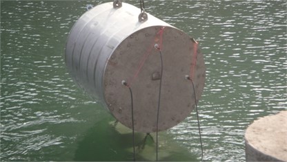
The tested structure is a 2.05-m-long model cylinder with double-layer shell. The outer shell has a 1.78 m diameter, and 2 mm thick; the diameter of its inner shell is 1.46 m, and the thickness is 8 mm. The shell is supported by four equally spaced annular plates. The shell model is airtight with 25-mm-thick stainless steel plates at both ends, and water is filled in the space between the inner and outer shells. In the interior of the inner shell, an 8 mm thick plate is fixed, on which a small air compressor (whose inlet and outlet valves are both open) and an actuator are mounted. Accelerometers are mounted near the feet of the compressor; a force sensor and an accelerometer are placed at the position of the actuator in contact with the plate. A power cable and two signal cables come out of the cylinder through three holes on an end plate.
Fig. 5The double-layer cylindrical shell model
The underwater impulse sound source used in this experiment is an electric spark impulse source, whose intensity may be adjusted by the charged voltage. For comparison, an electromagnetic sound source is also used, whose intensity is adjustable by a power amplifier. Hydrophones are also used to indirectly measure the volume velocity of source.
The model cylinder is suspended by a crane, and the underwater source and hydrophones are fixed to a boat with ropes. The water waves in the lake and background noise in the inlet is negligible, and the signal-to-noise ratio is high enough to meet the experimental requirements.
The following procedure is designed and implement in the experiments, according to the theoretical analysis introduced in Section 2:
(1) Suspend the model cylinder underwater, and fix the underwater impulse source to the boat and with 5.7 m distance away from the model. Mount each hydrophone at four symmetrical locations 2 m away from and around the source.
(2) Trigger the source to generate an impulse sound, and record and analyze the sound pressure response around the source and the acceleration response in the model. (Because the energy of the impulse is too concentrated in the time domain, the source should be carefully controlled: too weak impulse intensity may bring low signal-to-noise ratio, and too strong intensity may lead to outrange signals in the sensors, such as hydrophones and accelerators and induce nonlinear behaviors of sound propagation and vibration.
(3) Replace the impulse source with an electromagnetic sound source at the same location, and start the source to generate a signal with frequency sweeping from 80 Hz to 750 Hz. Likewise, record and analyze the sound pressure around the source and the acceleration response in the model.
(4) Replace the electromagnetic source with a hydrophone at the same location.
(5) Activate the actuator in the model with a powered signal with frequency sweeping from 80 Hz to 750 Hz. Record and analyze the actuating force and the radiated sound pressure detected by the hydrophone mentioned in step (4).
(6) Start the air compressor, and record and analyze the acceleration signal recorded by the accelerometer at the feet and the radiated sound pressure detected by a hydrophone located at the original source position.
(7) Substitute the data acquired in step (2), (5) and (6) into Eqs. (16-17) to derive the impulse-based reciprocal transfer functions and predict the radiated sound pressure.
For the validation of the proposed method, the sweep-based reciprocal transfer functions are obtained by substituting the data acquired the electromagnetic sound source in step (3) for the data acquired with the impulse sound source in step (2). The data acquired in step (5) and (6) are then substituted into Eq. (5) to derive the directly measured transfer functions and the radiated sound pressure.
3.2. Results and discussion
Firstly, Fig. 6 shows the effect of time-gate operation on the indirectly measured volume velocity of impulse sound source. For the convenience of discussion, define the sound pressure signals without time-gate processing as the original sound pressure signals, and the volume velocity computed with these signals is defined as the original volume velocity. Likewise, define the sound pressure signals after time-gate processing as the corrected sound pressure signals, and the volume velocity derived from these signals as the corrected volume velocity. Fig. 6(a) and Fig. 6(b) show the original and corrected sound pressure signal in the time domain, respectively. The corrected sound pressure signal is more close to an ideal impulse signal.
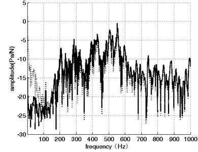
The spectra of both sound pressure signals are also shown in Fig. 7. The frequency distribution of the correct sound pressure signal is flatter than that of the original signal. The original signal is more affected by reflection and scattering, so its spectrum contains peaks and troughs.
Secondly, the time-gate operation is also found to have improved the accuracy of the impulse-based reciprocal measurement of transfer functions. For the convenience of discussion, define the transfer functions derived from the original volume velocity as the original impulse-based reciprocal transfer functions (OIRTF), define the transfer functions derived from the corrected volume velocity as the corrected impulse-based reciprocal transfer functions (RIRTF), and define the transfer functions derived from the signals measured with the electromagnetic sound source as the sweep-based reciprocal transfer functions (SRTF), for which the influences of the reverberant field have been eliminated with traditional methods. The influence of the inhomogeneous sound field is eliminated by averaging the data collected by four hydrophones. The overshoot of sound energy density is also corrected based on the average sound-absorption coefficient of the inlet derived with the sound pressure measured in step (3). Finally, the corrected sound pressure data is used to calculate the source volume velocity before SRTF is derived. The details of the correction steps are introduced in reference [11].
Fig. 6Sound pressure signals in the time domain
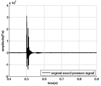
a) Original signal
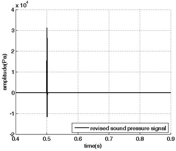
b) Corrected signal
Fig. 7Sound pressure signals in the frequency domain
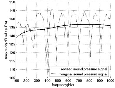
Fig. 8The reciprocal transfer functions of the actuator obtained with three methods
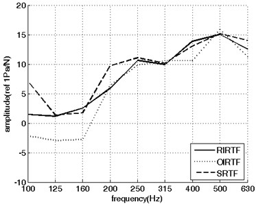
Fig. 8 shows the transfer function of the actuator obtained with the three methods mentioned in the last paragraph. In most frequency bands, compared with OIRTF, RIRTF is closer to SRTF, especially in the low frequency bands, where the effect of time-gate processing is significant. In most frequency bands, the gap between the RIRTF and SRTF is less than 2 dB.
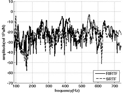
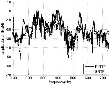
Similar results are also obtained for the reciprocal transfer functions at the feet of the air compressor, as shown in Fig. 9. At most frequencies, the gap between the RIRTF and SRTF is less than 3 dB. However, the error becomes larger at some peaks because of the existence of background noise in the inverse problem [15].
Hence the time-gate processing helps to improve the accuracy of the impulse-based reciprocal measurement of transfer function to be close to that of the sweep-based reciprocal measurement with electromagnetic source. Moreover, with an impulse sound source, the actuating time is reduced and the actuating frequency band is wide. Consequently, compared with the sweep-based measurement, the time efficiency of the impulse-based measurement is also improved.
Fig. 9The reciprocal transfer functions from the location of noise measurement to the feet of air compressor
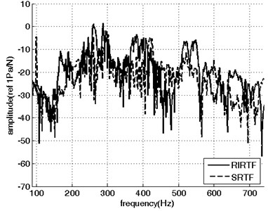
a) measuring point of foot B at landscape orientation
b) measuring point of foot D at landscape orientation
c) measuring point of foot A at axial orientation
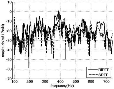
d) measuring point of foot C at axial orientation
e) measuring point of foot C at vertical orientation
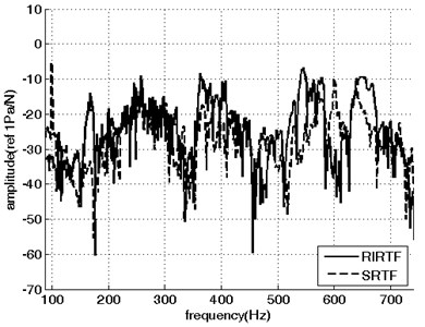
f) measuring point of foot D at vertical orientation
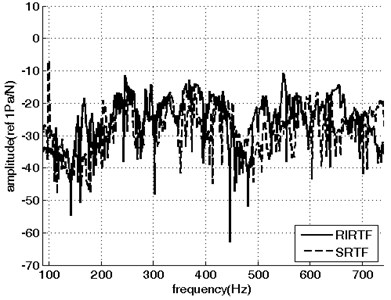
Finally, the transfer functions of the actuator obtained by impulse-based reciprocal measurement and direct measurement are compared in Fig. 10. The deviation of the reciprocal measurement result from the directly measured result is less than 5 dB in most tested frequency bands (the total frequency range is constrained by the electromagnetic sound source and actuator).
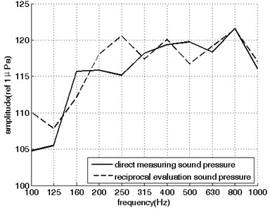
When the sound source is the air compressor, the sound pressure predicted using Eq. (17) and the radiated sound pressure directly measured in step (6) are compared in Fig. 11. The analyzed frequency range is determined by the sampling frequency, which is 3200 Hz, because the air compressor and impulse source have wider frequency range. Owing to the limited accuracy of the reciprocal measurement technique, the gap between the direct and reciprocal result is larger.
The proposed method can achieve accuracy similar to the traditional reciprocal measurement, and in comparison, with direct measurement, the results are still affected by many other factors. In total frequency range, the RIRTF is still larger than the direct transfer function. Based on the theory of Section 2, this error can be reduced with a better impulse sound source and more accurate reciprocal measurement.
Fig. 10The RIRTF and the direct transfer functions of the actuator
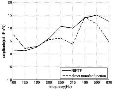
Fig. 11The reciprocal predicted sound pressure versus the directed measured sound pressure
4. Conclusions
In this paper, an impulse-based reciprocal method is proposed to measure the transfer functions of underwater structure in situ, and the influences of the reverberant sound field are eliminated by an operation with time gates. This method is numerically verified, and then validated by a lake experiment on an actuator and an air compressor. Major conclusions of this study are listed as follows:
1) The proposed method can achieve similar accuracy and higher time efficiency compared with the traditional reciprocal measurement at most frequencies, with error less than 3 dB;
2) The influences of the reverberant field on the volume velocity can be eliminated conveniently with the proposed method, and measurement of the average sound-absorption coefficients and complex signal processing are not required;
A limitation of this method is the difficulty in controlling the intensity of the impulse source, and an automatically controlled impulse source will be expected.
References
-
Wolde T. T. On the validity and application of reciprocity in acoustical, mechauto-acoustical and other dynamical systems. Acustica, Vol. 28, 1973, p. 23-32.
-
Lyamshev L. M. Reciprocity principle and its applications in underwater acoustics. The 14th International Conference on Acoustics, Beijing, 1992.
-
Fahy F. J. The vibro-acoustic reciprocity principle and applications to noise control. Acustica, Vol. 81, 1995, p. 544-558.
-
Musha T., Kikuchi T. Numerical calculation for determining sonar self-noise sources due to structural vibration. Applied Acoustics, Vol. 58, 1999, p. 19-32.
-
Mencik J. M., Champoux Y., Berry A. Development of a blocked pressure criterion for application of the principle of acoustic reciprocity. Journal of Sound and Vibration, Vol. 245, Issue 4, 2001, p. 669-684.
-
Godin O. A. Calculation of amplitudes of acoustic normal modes from the reciprocity principle. Journal of the Acoustical Society of America, Vol. 119, Issue 4, 2006, p. 2096-2100.
-
Sum K. S., Pan J. On the steady-state and the transient decay methods for the estimation of reverberation time. Journal of the Acoustical Society of America, Vol. 112, Issue 6, 2002, p. 2583-2588.
-
Ducourneau J., Faiz A., Khanfir A., Chatillon J. Measuring sound scattering coefficients of uneven surfaces in a reverberant workplace – principle and validation of the method. Applied Acoustics, Vol. 74, 2013, p. 653-660.
-
Sanchez J., Benaroya H. Review of force reconstruction techniques. Journal of Sound and Vibration, Vol. 333, 2014, p. 2999-3018.
-
Janssens M. H. A., Verheij J. W., Loyau T. Experimental example of the pseudo-forces method used in characterisation of a structure-borne sound source. Applied Acoustics, Vol. 63, 2002, p. 9-24.
-
Cheng G., Xu R., He L., et al. Application and measurement of underwater acoustic reciprocity transfer functions in reverberant. Chinese Journal of Acoustics, Vol. 33, Issue 4, 2014, p. 369-378.
-
Berkhout A. J., D. De Vries, Vogel P. Acoustic control by wave field synthesis. Journal of the Acoustical Society of America, Vol. 93, Issue 5, 1993, p. 2764-2778.
-
Cheng G., Xu R., He L. Application and measurement of underwater acoustic reciprocity transfer functions with impulse sound sources. Vibroengineering Procedia, Vol. 5, 2015, p. 48-52.
-
Wolde T. T. Reciprocity measurements in acoustical and mechano-acoustical systems – review of theory and applications. Acustica United with Acustica, Vol. 96, 2010, p. 1-13.
-
Lu L., Sun H., Wu M. Improvement of reciprocity measurements in acoustical source strength. The 21st International Congress on Sound and Vibration, Beijing, China, 2014.
About this article

