Abstract
To study the seismic behavior and post-earthquake repairability of coupled shear wall with concrete filled steel tube (CFST) frame and concealed partitioned steel plates (SPs), three 1/5 scaled coupled shear wall specimens were designed with different type of CFST column or core structure. Low-cycle reversed loading was adopted in the test. The test contained two stages. Load-carrying capacity, energy dissipation, ductility, stiffness and failure characteristic of the specimens were compared in pre-repair stages and post-repair stages. The conclusions are drawn that the core structure shows a good ductile yielding mechanism. The cross-section type of frame has an obvious effect on the seismic behavior of shear wall. After damage and strengthening, the new coupled shear wall still has enough seismic capacity and good energy dissipation capacity, and it is easy to be repaired after earthquake. Finite element analysis software ABAQUS has been used to simulate the behavior of coupled shear wall. Ultimate strength is obtained with the vibration of thickness of SPs.
1. Introduction
A coupled shear wall with concrete filled steel tube (CFST) frame and concealed partitioned steel plates (SPs) consists of CFST side columns, steel reinforced concrete (SRC) concealed columns, partitioned SPs concealing within wall limbs, partitioned SPs concealing within beams, concrete coupling beams, concrete walls and connection components. CFST frame and SRC concealed columns constitute the core structure of platoon SRC columns. With SPs embedded wall limbs and coupling beams, the core structure of platoon SRC columns forms the core structure of “Platoon SRC columns-partitioned SPs concealing within walls-partitioned SPs concealing within beams”. The concealed SPs strengthen the interconnection of platoon SRC columns greatly and work synergistically with concrete coupling beams and walls to consume seismic energy. The coupled shear wall integrates platoon SRC column, concealed partitioned SPs and reinforced concrete (RC) coupled shear wall system, and adopts two different materials of steel tube and concrete. Besides, the rigidity of coupling beams well corresponds to that of coupling wall limbs, to assure the lateral stiffness of the structures. The bending resistance and axial force of each wall limb form stress couple to resist horizontal force. The coupled shear walls with various superior combinations have multiple seismic fortification lines.
Composite shear wall has been studied at home and abroad. Nie [1-3] carried out experiments on two 1:5 scale 2-bay, 5-storey SPSW specimens with circular CFST columns without openings and three specimens with square CFST columns and openings, according to the Jinta Tower in Tianjin as a practical case, and results show that SPSW structure with openings has the satisfying seismic behavior and high loading capacity. Guo and others [4-6] tested two-storey and three-storey steel plate shear walls, in which the research results show that SPSW structures can increase energy dissipation capacity and ductility under lateral loads with concrete filled steel tube frame. Li and others [7] studied the seismic behavior of a 40 % scale two-and-half-storey C-SPSW specimen, showing that the damage of the coupling beam can be limited to predetermined positions as the mechanism of plastic deformation for design. Patricia M. Clayton [8] analyzed the behavior of the two-storey self-centering steel plate shear wall under quasi-static loading. W. S. Park and H. D. Yun [9, 10] carried out analytical and experimental studies to develop the strength equations of steel coupling beams-concrete wall connections. J. W. Berman and M. Bruneau [11] performed an experimental study on light gauge SP shear walls. Yamada [12] compared mechanical performances of steel plate shear wall with outer closed RC through experiment. The result shows that its seismic behavior remarkably improved.
M. R. Javaheri-afti and others [13] conducted experimental study on cold-formed steel walls sheathed by thin steel plates. W. L. Cao [14-16] carried out two stages of low-cycle reverse tests on sixteen specimens of a multi-energy dissipation composite shear wall and the analyzed results show that steel plate (SP) deep beams and energy dissipation strips have significant influence in energy dissipation; the composite shear wall exerts multiple anti seismic lines. The real structural seismic damage is simulated successfully with the shaking table test model. The experimental results can reflect the actual situation. However, there are numerous limitations in a shaking table test such as small table facet bearing capacity, high costs and more complicated technology. Compared with the shaking table test, the low cyclic loading test method is simpler and its costs are lower. The method can maximize testing the development process of the test pieces under load effects. Such a test method not only can provide a basis for static structural analysis, but also provide an indirect basis for certain dynamic analysis. A majority of normative seismic provisions at home and abroad are currently based on such a test result. Therefore, the low cyclic loading test method is used in the thesis to study the seismic behavior of shear wall specimens.
In this paper, CFST columns – concealed partitioned SPs coupled shear wall is proposed. To compare the influence of different structures on seismic behavior, 3 specimens are designed for low cyclic loading test. Each specimen’s failure characteristics, hysteretic characteristics, carrying capacity and ductility are analyzed and the design method of seismic structure is studied. A finite element model of coupled shear wall with concrete filled square steel tube frame corresponding to the stage I test was established under the monotonic loading condition and through using ABAQUS finite element analysis software. The numerical simulation and analysis for the specimens with different parameters were performed, and the stress contour and skeleton curves of different parameters were obtained.
2. Experimental introduction
2.1. Specimens design
The test contained two stages. In stage I test, the reduction scale for the coupled shear wall specimen with CFST columns was designed as 1:5. The three specimens had the same overall dimensions. There were 4 storeys, with a total height of 3900 mm, a width of 1875 mm, a thickness of 100 mm, a shear span ratio of 1.68 and a couple beam span-depth ratio of 1:1. Table 1 sets forth main parameters of each specimen. , respectively refer to the reinforcement ratio of wall limb and coupling beam in Table 1. Considering the influence of different section forms of CFST columns and layout of partitioned SPs on the seismic behavior, specimen SCSW1-I was designed as a coupled wall with square CFST columns, without steel plate in the wall limb and coupling beam. Specimens SCSW2-I and SCSW3-I were designed as a coupled wall with square CFST columns and a coupled wall with circular CFST columns respectively, and these two specimens had concealed partitioned SPs (span-depth ratio: 1.0) in the wall limb and coupling beam. All the partitioned SPs had the same layout.
The side columns of the specimens were designed at equal area and equal steel ratio. The section size of square steel tube was 160×4, and the section size of circular steel tube was Φ180×4.5. The section of steel overlapping concealed columns was 160 mm×100 mm, with H-shaped steel 120×60×8×10, and 4Φ10 longitudinal bars. The thickness of partitioned SPs between the first and second storey coupling beams and wall limbs was 3mm, and the thickness of that between the third and fourth storey was 2 mm. Carrying capacity and stiffness matched well with heights. Steel tubes and H-shaped steel columns were Q345 steel, and steel plates were Q235 steel. Cold-drawn bars Φ4 were used for distributing bars in wall boards, steel tie bars, longitudinal bars in coupling beams and stirrups in coupling beams and SRC concealed columns. The 3 specimens had the same reinforcement ratio and the same layout of steel bars. Tie bars passed through gaps between the up and down partitioned steel plates. The longitudinal bars in coupling beams were welded with steel tube wall of side columns by the right-angle bending segments at the two ends of the bars, and they also worked as horizontally distributed bars of wall board. Fig. 1 shows the geometric dimensions and structures of the specimens.
Table 1Parameters of specimens
Specimen No. | Wall limb | Coupling beam | Overall steel ratio (%) | |||||
Steel plate 2 mm | Steel plate 3 mm | Steel ratio (%) | 2 mm steel ratio (%) | 3 mm steel ratio (%) | ||||
SCSW1-I | 0.35 | 0 storey | 0 storey | 6.19 | 0.47 | 1.03 | 1.03 | 5.74 |
SCSW2-I | 0.35 | 2 storeys | 2 storeys | 7.14 | 0.47 | 2.87 | 3.79 | 6.84 |
SCSW3-I | 0.35 | 2 storeys | 2 storeys | 7.08 | 0.47 | 2.87 | 3.79 | 6.78 |
Fig. 1Dimension and details of specimens
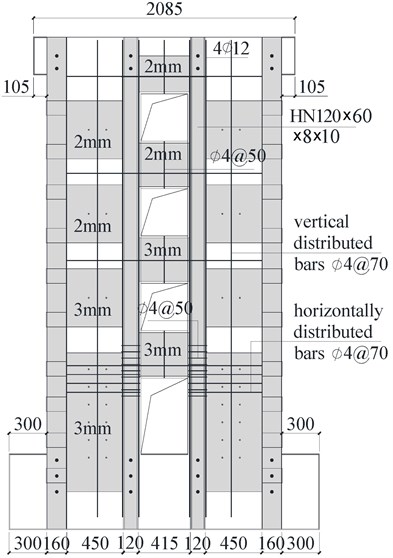
a) SCSW2-I structural arrangement
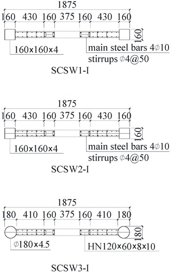
b) Section forms and steel bars of the specimens
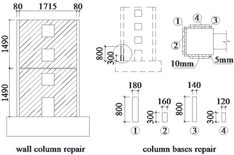
In stage II test, the specimens damaged in stage I were repaired and regarded as new specimens. The numbers of new specimens (SCSW1-II, SCSW2-II, SCSW3-II) were corresponding to the numbers of stage-I specimens. Based on characteristics of different damages, the repair was also different: welding steel plates to column base and wall limb. The welding of steel plates at square CFST column base belongs to bending resistant repair. It adopted full welding and welded a layer of steel plate with a thickness of 5 mm, outside of which was welded a layer of steel plate with a thickness of 10 mm. The bottom edge of the repairing steel plates was reliably welded with foundation beam, to make sure that the forces of upper structure be effectively transferred to the foundation beam. The welding of 3 mm thickness thin steel plates within side column steel tubes belongs to shear resistant repair. The thin steel plates were divided into upper and lower ones, with each at the position of opening holes. Inter-columnar thin steel plates were welded to the wall limbs of specimen SCSW1-II and SCSW3-II, and no repair was conducted to the column base. SCSW2-II adopted comprehensive repair, and after the column bases were repaired, the inter-columnar thin steel plates were welded. Fig. 2 shows the design of repair methods.
Fig. 2Repair method
2.2. Measured property of materials
The specimens were cast with fine aggregate concrete in three operations and the strength grade of which was designed as C45. The average measured cube compressive strength of concrete was 48.2 MPa, and the elastic modulus was 3.38×10⁴ MPa. Table 2 sets forth the measured properties of steel plates and steel bars. denotes yield strength, denotes ultimate strength and denotes elasticity modulus.
2.3. Test program and test point arrangement
Test program: In order to study the seismic resistance and post-earthquake reparability of the type of coupled shear walls, the test was divided into 2 stages. In stage I, the measured displacement drift was increased to 1/50 and the horizontal displacement was 63 mm. The specimens yielded and got damaged, but were not broken completely. The specimens damaged in stage I were repaired and taken as new specimens for the stage II test.
Low cyclic loading test was carried out to the 3 specimens. First, the vertical load was 1500 kN, which gave an axial compression ratio of 0.3 for all specimens, and kept it unchanged during the test. Later, by the hydraulic actuator, the low cyclic lateral load was applied to the center of the load beam which is 3150 mm away from the foundation top. Fig. 3 is the sketch of the loading devices. In stage I, the lateral load was adopted by force-displacement mixed control loading method. Lateral loading based on force control was adopted, until yielding phenomenon of coupled shear walls occurred. Subsequently, lateral load was controlled by load and displacement. In stage II, lateral load was controlled by displacement. When the lateral load decreased to lower than 85 % of the maximum load, the loading was discontinued. During the loading, a two-step cyclic loading scheme was implemented, in which a load control program was used prior to yield load and a displacement control program was used following the yield point.
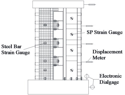
Test point arrangement: A horizontal displacement gauge was arranged at the ends of load beam which is 3150 mm from the foundation top. Dial indicators were arranged at the side and top of the foundation to measure the horizontal slippage of the foundation and the upwarp of the foundation bed. Force sensors were put at the ends of vertical jack and horizontal jack. Strain measure points were respectively arranged at the bottom of steel tubes, the bottom of H-shaped steels, the middle of partitioned SPs, the bottom of vertical distributed steel bars, the middle of horizontal distributed steel bars, and the ends and middle of coupling beam longitudinal bars, as shown in Fig. 4.
Table 2Mechanical properties of steel bar and steel
Steel | Used location | (MPa) | (MPa) | (MPa) |
160×4 square steel tube | Steel tube side column | 348.45 | 515.67 | 2.05×10⁵ |
Φ180×4.5 circular steel tube | Steel tube side column | 379.97 | 510 | 2.04×10⁵ |
10 mm steel plate | H-shaped steel in concealed column, welded steel plate | 405.55 | 496.56 | 2.04×10⁵ |
8 mm steel plate | H-shaped steel in concealed column | 378.06 | 536.07 | 2.05×10⁵ |
3 mm steel plate | Partitioned SPs, welded thin steel | 268.76 | 399.26 | 2.01×10⁵ |
2 mm steel plate | Partitioned SPs | 252.03 | 389.01 | 2.05×10⁵ |
Φ10 steel bar | Longitudinal bar in concealed column | 315.7 | 436.85 | 2.05×10⁵ |
Φ4 steel bar | Distributed steel bar | 634.06 | 738.05 | 2.06×10⁵ |
Fig. 3Sketch of loading devices
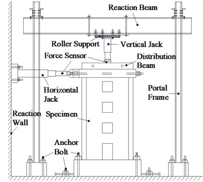
Fig. 4Arrangement of test points
Data collection: All loads, displacements and strain data were automatically collected with IMP data acquisition system. The cracks formation and spalling of concrete, steel bars yield, SPs yield and the failure characteristics of each component were observed and recorded manually.
3. Test result and analysis
3.1. Failure phenomenon
3.1.1. Stage I test
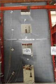
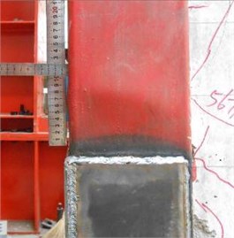
Fig. (5) demonstrates the failure modes of each specimen in stage I. The damage and failure characteristics are as follows:
1) Failure mode. The failure types of three coupled shear walls were bending-shear damage. The overall damage of four coupling beams was heavier than that of wall limbs. The damage mechanism was “strong wall limb – weak coupling beam”. Each specimen had similar damage process but different damage degrees. Compared with specimen SCSW1-I, two specimens with partitioned SPs had much more concrete cracks evenly distributed in the entire wall and better seismic behavior. Shear movement happened among the concrete wall limb, CFST frame and SRC concealed columns of each specimen. Small crossing diagonal cracks emerged at the connecting interfaces between the concrete walls and the core steel structure. With the exertion of cyclic load, the number and size of diagonal cracks increased, and the concrete of bilateral wall limbs got crushed gradually. Four vertical energy-dissipation strips were formed to ease the damage to steel tube concrete and concealed SPs. It can guarantee that the core structure will fully realize their aseismic consumed energy ability in the final stage. This is an important representation of the design concept of damage-reduction and energy dissipation for the new composite coupled wall.
2) In the stage of crack initiation, 3 specimens had similar cracking sequences. The first bending cracks occurred at the two ends of coupling beam, and then bending horizontal cracks took place in the bottom of wall limb due to tension, afterwards shearing diagonal cracks appeared in coupling beams and wall limbs. The coupling beams of specimen SCSW1-I on the first floor were tested without diagonal cracks. For specimens SCSW1-I, SCSW2-I and SCSW3-I, the initial crack loads at the end of coupling beams were respectively 124 kN, 141 kN and 142 kN, with the corresponding displacement drifts of 1/1445, 1/1350 and 1/1318. They had similar sequences of cracking position. First, it was the second floor of coupling beams in the middle, followed by the first and third floor of coupling beams and finally it was the top floor of coupling beams. For the three specimens, the horizontal crack loads of wall limb were respectively 150 kN, 160 kN and 163 kN, with corresponding displacement drifts of 1/892, 1/1164 and 1/1107. Specimens with concealed partitioned SPs had larger transformed areas of wall limb sections and greater crack loads.
3) In the yield stage, the ends of coupling beams first developed plastic hinge, and the corner concrete spalled off slightly. Then under bending moment, the steel bars and frame steel tube at the bottom of tension-side wall limb yielded, and the yielding area gradually expanded upwards. With displacement drift 1/295 (318 kN), the concrete on 4 energy-dissipation strips of SCSW1-I was peeled and dropped dregs. The yield displacement drifts () of SCSW2-I and SCSW3-I were respectively 1/159 (641 kN) and 1/160 (656 kN). Diagonal cracks distributed all over wall limbs. Diagonal shear cracks of each floor coupling beam expanded completely, and connected with diagonal cracks in wall limbs. The tensile steel tube reached its yielding strain. Through reasonable design, CFST side column will yield and consume energy firstly instead of buckling, performing good seismic behavior. The arrangement of core structure could postpone the formation of plastic hinge at the bottom of wall limbs.
4) In the buckling stage, with 1/50 (385 kN), the coupling beams of specimen SCSW1-I got damaged, with the upper part being more serious than the lower part. Concrete of the 3rd floor coupling beam spalled off and the bars got exposed. Steel plates at the bottom of pressure-side steel tube frame had slight local buckling. Due to buckling under compression, bulging deformation of about 4 mm happened and 4 vertical energy-dissipation strips run through the wall limbs. The strip concrete spalled off to a great extent, and the welding spots of several horizontal bars were ruptured. As for the two specimens with concealed partitioned SPs, the concrete in the middle of coupling beam chunks spalled off, and energy-dissipation strips were formed in the upper part of wall limbs. The function of damage-reduction and energy-dissipation is inferior to that of specimen SCSW1-I. For specimen SCSW2-I, with 1/50 (799 kN), due to buckling under compression, bulging deformation of about 10 mm happened to steel plates at the bottom of steel tube frame. For specimen SCSW3-I, with 1/50 (866 kN), due to buckling under compression, the bulging deformation of about 4 mm happened to steel plates at the bottom of steel tube frame, and the energy-dissipation strips got slightly damaged. The steel tube of CFST side column at bottom exhibited yielding before buckling. It occurred firstly intensity failure instead of instability failure. The CFST column failed by the local buckling which caused by the material strength damage. The eventual failure of structure is that the geometrical unstable system is forming, and the bearing capacity is no longer in increment. The failure modes of the 3 coupled shear walls were similar: the ends of coupling beams formed plastic hinges which caused by the bending destruction; the steel tubes of CFST side column, the steel bars and partitioned steel plates at the bottom of tension-side wall limb yielded in tension; the steel tubes formed plastic hinges and the concrete at the bottom of pressure-side wall limb failed in compression. Specimen damage caused by compression buckling in the CFST column bottom belongs to ductile failure and large eccentric compression. The core structure of “Platoon SRC columns – concealed partitioned SPs”, as the second seismic defense line, collaborated with concrete walls and vertical energy-dissipation strips to resist earthquake and consume energy. The more stable the whole specimen is, the weaker the damage-reduction function of the energy-dissipation strips are, and the greater the bulging deformation of steel tube frame is.
Fig. 5Failure modes of specimens in stage I test
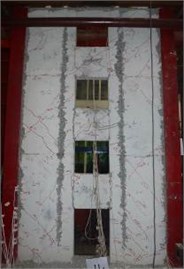
a) SCSW1-I
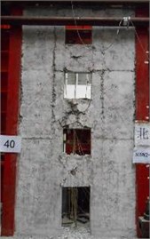
b) SCSW2-I
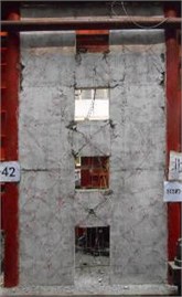
c) SCSW3-I
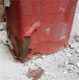
d) SCSW2-I column base damage
3.1.2. Stage II test
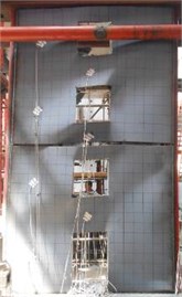
Fig. (6) demonstrates the failure mode of each specimen in stage II. The damage and failure characteristics are as follows:
1) When the displacement drift is increased to 1/105, the repairing thin steel plates of specimen SCSW2-II formed diagonal tension ribbons along the diagonal line of opening. When the displacement drift is increased to 1/85, the column-base-unrepaired specimen SCSW1-II and SCSW3-II formed diagonal tension ribbons of the thin steel plates. When the displacement drift is increased to 1/50, thin steel plates yielded drastically, and the concrete at the bottom of wall limbs of specimen SCSW1-II got crushed, the steel tubes above the repairing thick steel plates at the wall limbs of specimen SCSW2-II bulged out, and for specimen SCSW3-II,the column base of circular steel tube frame on the negative tension side was torn apart. When the displacement drift is increased to 1/35, the steel tubes in side columns of all specimens bulged out seriously, and rips of different sizes appeared at four corners of thin steel plate openings.
2) The damage of repairing thin steel plate at wall limbs of specimen SCSW1-II is more serious than that of other specimens. It indicates that anti-shear repair of the composite wall limb by welding thin steel plate can receive good effect. With the increase of steel content, the effect of such repair method weakens, and has a relatively high capacity of energy-dissipation in weaker core structures. After the column bases of SCSW2-II are welded with repairing steel plate, the bottom wall limbs receive lighter damage, and could avoid stop of work in advance due to excessive bending moment at the bottom of coupled walls. Based on different structures and bending-shear damage modes, different measures are taken for repair. For SCSW2-II with partitioned SPs, the steel tube in the side column is square. In comparison with specimen circular CFST column SCSW3-II, it is more convenient for column base repair, and the damage degree of each component is even. Besides, it has a better capacity of damage-reduction and a good repairability.
Fig. 6Failure modes of specimens in stage II test
a) SCSW1-II
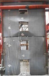
b) SCSW2-II
c) SCSW3-II
d) SCSW2-II column base damage
3.2. Hysteretic behavior
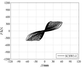
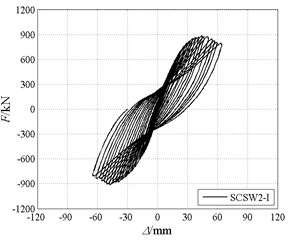
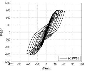
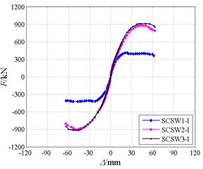
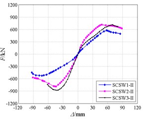
Fig. 7 and Fig. 8 show the hysteretic curves and skeleton curves for specimens.
1) Stage I test: Fig. 7 shows that specimen SCSW1-I has obvious pinch phenomenon of hysteresis curve. With poor energy-dissipating capacity, it shows strong shear and slippage hysteretic characteristics. With coexistence of bending and shear, the hysteretic loops of SCSW2-I and SCSW3-I are plump in arch shapes. It suggests that, with steel tube concrete frames of different section forms, coupled shear walls with partitioned SPs have better energy-dissipating behavior. The hysteretic loop of SCSW2-I is a little more pinched than that of SCSW3-I. The reason is that circular CFST column has a higher shear resistance than square CFST column, and could provide better constraints to wall-board.
The skeleton curves show the similar characteristics of ascending curves observed in tests of the 3 specimens. Compared with SCSW1-I, SCSW2-I and SCSW3-I with concealed SPs have a longer process of development from yield load to ultimate load as well as a higher emergency capacity. When the displacement drift is less than 1/1300, the skeleton curves take on linear shape, and no residual deformation happens. When the displacement drift is greater than 1/60, the stiffness degrades remarkably, the horizontal loads increase stably and residual deformations happen after unloading. When the displacement drift develops into 1/50, the stage I test comes to an end, and each specimen displays marked residual deformation. At the later period of loading, the stiffness of SCSW2-I and SCSW3-I degrades, and the skeleton curves have descending curves of various degrees. The descending curve of square CFST column coupled wall is steeper than that of circular CFST column coupled wall. It suggests that under the same section area and steel content, the difference in section forms of platoon SRC edge components has certain influence on the later-period carrying capacity of the composite coupled walls. But on the whole, these two specimens have good ductility and energy-dissipation behavior.
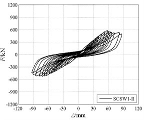
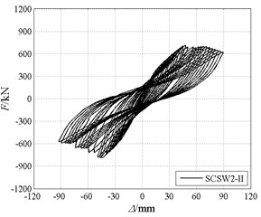
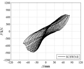
2) Stage II test: Fig. 8 shows that after comprehensive repair, the energy-dissipation capacities of specimens are recovered to different extents. The hysteretic curve of specimen SCSW1-II is much fuller than that of SCSW1-I, and the energy-dissipation capacity is higher. Specimen SCSW2-II has a relatively good repair effect, though the ultimate load and stiffness decline a little. The circular steel tube of specimen SCSW3-II is not repaired. With excessive bending moment of damaged circular steel tube frame at the negative tension side, steel plates at column bases get torn apart at an earlier time and the concrete in the steel tube gets crushed, causing carrying capacity to fall suddenly. Afterwards, only positive cyclic loading is conducted to SCSW3-II.
Fig. 7Hysteretic curves and skeleton curves of specimens in stage I test
a)
b)
c)
d)
Fig. 8The whole-process hysteretic curves and skeleton curves of specimens in stage II test
a)
b)
c)
d)
The skeleton curves of repaired coupled walls are contrasted in Fig. 8. The figure shows that the skeleton curves of repaired walls are similar and have no yielding point. The positive and negative ultimate loads of repaired SCSW1-II improve substantially. Compared with SCSW2-II, the steel tube frame on one side of SCSW3-II ceases working much more early. It is hard to receive symmetric positive and negative damages. The stability in the later period is relatively poor. The comprehensive seismic behaviors of SCSW2-I and SCSW2-II are relatively better than those of other specimens.
3.3. Carrying capacity
Table 3 summarizes the load characteristics of the 3 specimens. The values in the table are the mean value of positive and negative absolute values. Failure load in stage I is corresponding to the 1/50 displacement drift at the end of the test. For the failure displacement is less than the deformation that corresponds to 85 % of the ultimate load, the displacement ductility factor is not calculated. The concrete walls have cracked completely in stage I, so there are no data about the cracking period in stage II. is the value of horizontal load which drops to lower than 85 % of the ultimate load.
An analysis of Table 3 shows that:
1) In stage I test, the yield load, ultimate load and failure load of SCSW2-I are respectively 101.6 %, 115.3 % and 107.5 % higher than those of SCSW1-I, indicating that the stronger core structure contributes a lot to the enhancement of carrying capacity. The section form of platoon SRC columns influences the load and stiffness of coupled wall. With the same section area and steel content, the cracking load, yield load and ultimate load of coupled wall with square CFST columns are lower than those of coupled wall with circular CFST columns. Strength-yield ratio is the ratio of ultimate load and yield load . SCSW1-I has a smaller strength-yield ratio, and the two coupled walls with concealed partitioned SPs have similar higher strength-yield ratio, and have the longer yield segment with restriction. It suggests that partitioned SPs concealed within coupled walls with SRC frames of different section forms have great emergency stock of bearing capacity and contribute to meeting seismic fortification standard of “no collapse under strong earthquake”.
2) Stage II test. The yield load and ultimate load of SCSW1-II are respectively 13.2 % and 32.2 % higher than that of SCSW1-I. The yield load and ultimate load of SCSW2-II are respectively 17.9 % and 16.3 % lower than that of SCSW2-I. The yield load and ultimate load for SCSW3-II are increased respectively by 12.2 % and 12.8 % in comparison with SCSW3-I. The strength-yield ratio of SCSW1-II is higher than those of the other 2 specimens, and is remarkably higher than SCSW1-I. This suggests that: damage repair plays an effective role in improving the carrying capacity of stage II. After repair, carrying capacity of a weaker core structure is much distinctly increased.
Table 3Load characteristics of specimens
Specimen No | Stage | Cracking load (kN) | Yield load (kN) | Ultimate load (kN) | Failure load (kN) | |
SCSW1-I | Stage I | 125 | 318 | 417 | 385 | 1.31 |
SCSW2-I | 141 | 641 | 898 | 799 | 1.40 | |
SCSW3-I | 142 | 656 | 915 | 866 | 1.39 | |
SCSW1-II | Stage II | – | 360 | 551 | 469 | 1.53 |
SCSW2-II | – | 526 | 752 | 645 | 1.43 | |
SCSW3-II | – | 576 | 798 | 724 | 1.39 | |
Note: – cracking load, – yield load, – ultimate load, – failure load, – yield strength ratio | ||||||
3.4. Displacement ductility factor
The following observations about displacements and ductility can be made from Table 4, and the results show that:
All the specimens have relatively high capacity of elastic-plastic deformation. The yield displacement drifts of SCSW1-I, SCSW2-I and SCSW3-I are respectively 1/295, 1/159 and 1/160. The average displacement drift of the two specimens with concealed partitioned plates is 1/160, which is approximately 1.8 times that of SCSW1-I without concealed partitioned SPs. The average peak displacement drift of the three specimens is 1/50, which is much higher than the limit value (1/120) of RC shear wall structure under violent earthquake. The definition of limit value is offered by the Code for Seismic Design of Buildings (GB50011-2010) [17].
Table 4Deformations of specimens
Specimen No. | Stage | Cracking load | Yield load | Ultimate load | Failure load | |||||
(mm) | (mm) | (mm) | (mm) | |||||||
SCSW1-I | Stage I | 2.2 | 1/1445 | 10.7 | 1/295 | 24.8 | 1/129 | 63 | 1/50 | — |
SCSW2-I | 2.3 | 1/1350 | 19.8 | 1/159 | 46.1 | 1/68 | 63 | 1/50 | — | |
SCSW3-I | 2.4 | 1/1318 | 19.6 | 1/160 | 47.8 | 1/66 | 63 | 1/50 | — | |
SCSW1-II | Stage II | – | – | 35.8 | 1/88 | 65.4 | 1/48 | 89.3 | 1/35 | 2.49 |
SCSW2-II | – | – | 24.0 | 1/131 | 46.2 | 1/68 | 78.3 | 1/40 | 3.27 | |
SCSW3-II | – | – | 28.3 | 1/111 | 56.3 | 1/56 | 69.9 | 1/45 | 2.47 | |
Note: – cracking displacement, – cracking displacement drift; – yield displacement, – yield displacement drift; – ultimate load displacement, – ultimate load displacement drift; – failure load displacement, – failure displacement drift; – displacement ductility factor, calculated by | ||||||||||
After repair, the yield displacement drifts of SCSW1-II, SCSW2-II and SCSW3-II are respectively 1/88, 1/131 and 1/111. SCSW3-II has the highest carrying capacity and lower ductility. The carrying capacity of SCSW2-II and SCSW3-II is close. The displacement ductility factor of SCSW2-II exceeds 3. Coupled wall with square CFST frame have the best ductility and deformation ability, similarly, the effect of comprehensive repair is good.
3.5. Energy-dissipation capacity
Table 5 sets forth the measured energy-dissipation of each specimen. is 1/50 displacement drift. is the displacement drift at failure point. is the value of energy dissipation, which is represented by the area of hysteretic curve.
Table 5Energy-dissipation capacity of specimens
Specimen No. | Stage | (MN·mm) | Ratio | (MN·mm) | Ratio | ||
SCSW1-I | Stage I | 1/50 | 36.057 | 1 | – | – | – |
SCSW2-I | 1/50 | 71.599 | 1.99 | – | – | – | |
SCSW3-I | 1/50 | 74.128 | 2.06 | – | – | – | |
SCSW1-II | Stage II | 1/50 | 29.030 | 1 | 1/35 | 60.584 | 1 |
SCSW2-II | 1/50 | 50.234 | 1.73 | 1/40 | 69.816 | 1.15 | |
SCSW3-II | 1/50 | 57.494 | 1.98 | 1/44 | 67.455 | 1.11 |
An analysis of Table 5 shows that: with 1/50 (63 mm), the energy dissipations of SCSW2-I and SCSW3-I are respectively 99 % and 106 % higher than that of SCSW1-I. This indicates that the hysteretic curve of specimens with concealed partitioned SPs is much fuller than that of specimens without concealed partitioned SPs. Therefore, if the constraint capacity of platoon SRC column core structure becomes stronger, the energy-dissipation capacity will become higher. In addition, the constraint effects of the core structure using steel tube frames with different forms of cross sections are some different. Under 1/50 displacement drift in stage II, the energy dissipations of SCSW2-II and SCSW3-II are respectively 73 % and 98 % higher than that of SCSW1-II. The high energy-dissipation capacity shows that the seismic energy dissipation capacities of coupled walls with platoon SRC frame are recovered effectively after repair by comprehensive methods.
4. Finite element modelling
The load – displacement curve under monotonic lateral loading and the skeleton curve under cyclic loading both can reflect the basic relationship between bearing capacity and deformation. In view of above-mentioned reasons, specimen SCSW2-I serves as basic specimen, and nonlinear finite element model is used to analyze the mechanical characteristics of specimen SCSW2-I under monotonic loading with ABAQUS.
4.1. Establishment of FEM model
3d solid element C3D8R is used to simulate the behavior of core concrete of CFST columns and concrete shear walls. Truss element T3D2 is used to simulate the behavior of steel bar in the coupling beams, walls and concealed columns. Shell element S4R is used to simulate the behavior of H-shaped steel in concealed column and steel tubes in side column. The behavior of partitioned SP is simulated by shell element S4R. The model of steel is hardening elastic-plastic model, and the concretes model is damaged plastic model with better convergence. Hard contact is adopted for normal direction of the interface between steel tube and concrete. Coulomb friction constitutive model is adopted for tangential direction of the interface, and the friction coefficient is taken 0.35. The concealed SPs in the coupling beams and wall limbs are merged into an integral part with H-shaped steels. The integral part and steel bars are all embedded in concrete shear wall. The core concrete of CFST columns and concrete shear walls bind with stiff foundation and load beam by TIE element.
4.2. Simulation of performance of SCSW2-I
The skeleton curves of specimen SCSW2-I in Stage I from both test and FEM modeling are shown in Fig. 9.
It can be seen from Fig. 9 that the simulation curve agrees well with the test result. The elastic rigidity of simulation curve is more than that of test curve, and the corresponding deformation of ultimate load is less than that of ultimate load in the test curve, that’s because the influences of the factors such as geometric defects, material damage etc. are not taken into full consideration in the finite element modeling.
Fig. 9Comparison between simulation curve and test curve of SCSW2-I
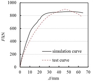
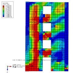
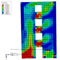
Fig. 10Stress nephogram of SCSW2-I and coupled shear wall model with concealed integral SPs
a) Concrete of SCSW2-I

b) Steel structure of SCSW2-I
c) Concrete of CISP coupled wall
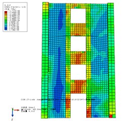
d) Steel structure of CISP coupled wall
4.3. Parametric study
Fig. 10 presents the stress nephogram of steel structure part and the damage nephogram of concrete wall when the concealed partitioned SPs coupled shear wall specimen SCSW2-I and the concealed integral SPs (CISP) coupled shear wall are at 1/50 angle of displacement. The CISP coupled shear wall has a higher steel ratio than specimen SCSW2-I with partitioned SPs. Compared with the concealed integral SPs coupled shear wall, the energy dissipation distribution of the concealed partitioned SPs of specimen SCSW2-I is more uniform, alleviating the damage degree of wall limb bottom and deferring damage course; the energy dissipation of the integral SPs in the wall limbs is concentrated in wall limb bottom, and the energy dissipation role of the upper SPs is not played well, so the bottom damage is more serious; the energy dissipation of the SPs of coupling beam in 2 models is sufficient, achieving the ductile yield mechanism of “strong wall limb, weak coupling beam”.
Fig. 11Influences of SPs’ thickness on coupled shear wall
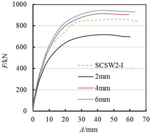
Fig. 11 shows the comparison of stress-strain relation curves between 2 mm, 4 mm and 6 mm thick partitioned SPs model and SCSW2-I model. It can be seen from Fig. 11 that the bearing capacity of the shear walls gradually increases with the increasing thickness of SPs. The initial rigidity of shear walls is somewhat improved, but the range is quite small. When the thickness of the partitioned SPs increases to a certain degree, the improvement degree of the bearing capacity is accordingly reduced. Therefore, the thickness and strength of partitioned SPs shall be reasonably determined in the design.
5. Conclusions
Through the study and analysis of the 2-staged low cyclic loading test on coupled shear walls with CFST columns – concealed partitioned SPs, the following conclusions are drawn:
1) For coupled shear walls with CFST columns - concealed partitioned SPs, its core structure of “Platoon SRC columns – partitioned SPs concealing within walls – partitioned SPs concealing within beams” realizes the ductile yield mechanism of “strong wall limb and weak coupling beam”. With full hysteretic curve and stable work performance, the seismic energy dissipation performance of the coupled shear wall is much better than that of the coupled shear walls with SRC frame.
2) The reasonable match of partitioned SPs and coupled shear wall with platoon SRC frames of different section forms can significantly improve the carrying capacity, deformation, ductility and energy-dissipation capacity of the coupled wall.
3) For the composite coupled shear wall with CFST columns – concealed partitioned SPs, after obvious yield damage, it can be repaired by welding thin steel plates in the steel tube and outside of steel tube column base. After repair, it still has high repairability.
4) The key of good repair effect lies in excellent handling of the strong and weak relationship between bending and shear as well as a full play of shear energy dissipation capacity of steel plates. The core structure of coupled shear walls with CFST frame is relatively weak. After reasonable matching and repair of the steel plates, the carrying capacity improves by 32.2 %, and the capacity of energy dissipation is better played.
5) The simulation result agrees well with the test result. Matching the strengths of the wall limb and coupling beams by designing the parameters such as steel ratio, the SPs’ thickness etc. properly are the key measures to ensure the ductile yielding mechanism.
References
-
Nie J. G., Li Z. Lateral stiffness of steel plate shear walls. Science China Technological Sciences, Vol. 57, 2014, p. 151-162.
-
Nie J. G., Zhu L., Fan J. S., Mo Y. L. Lateral resistance capacity of stiffened steel plate shear walls. Thin-Walled Structures, Vol. 67, 2013, p. 155-167.
-
Nie J. G., Fan J. S., Liu X. G., Huang Y. Comparative study on steel plate shear walls used in a high-rise building. Journal of Structural Engineering, Vol. 139, 2013, p. 85-97.
-
Guo L. H., Rong Q., Ma X. B., Zhang S. M. Experimental and analytical study of composite steel plate shear walls connected to frame beams only. Journal of Building Structures, Vol. 33, 2012, p. 59-68.
-
Guo L. H., Rong Q., Ma X. B., Zhang S. M. Analysis of composite steel plate shear walls connected with frame beams only. Structures and Buildings, Vol. 166, 2013, p. 507-518.
-
Guo L. H., Li R., Zhang S. M., Yan G. R. Hysteretic analysis of steel plate shear walls (SPSWs) and a modified strip model for SPSWs. Advances in Structural Engineering, Vol. 15, 2012, p. 1751-1764.
-
CLi H., Tsai K. C., Chang J. T., Lin C. H., Chen J. C., Lin T. H., Chen P. C. Cyclic test of a coupled steel plate shear wall substructure. Earthquake Engineering and Structural Dynamics, Vol. 41, 2012, p. 1277-1299.
-
Clayton P. M., Winkley T. B., Berman J. W., Lowes L. N. Experimental investigation of self-centering steel plate shear walls. Journal of Structural Engineering, Vol. 138, 2012, p. 952-960.
-
Park W. S., Yun H. D. Bearing strength of steel coupling beam connections embedded reinforced concrete shear walls. Engineering Structures, Vol. 28, 2006, p. 1319-1334.
-
Park W. S., Yun H. D., Hwang S. K., Han B. C., Yang I. S. Shear strength of the connection between a steel coupling beam and a reinforced concrete shear wall in a hybrid wall system. Journal of Constructional Steel Research, Vol. 61, 2005, p. 912-941.
-
Berman J. W., Bruneau M. Experimental investigation of light-gauge steel plate shear walls. Journal of Structural Engineering, Vol. 131, 2005, p. 259-267.
-
Yamada M. Steel panel encased RC composite shear walls. Proceedings of an Engineering Foundation Conference, Potosi, 1992, p. 899-912.
-
Javaheri-Tafti M. R., Ronagh H. R., Behnamfar F., Memarzadeh P. An experimental investigation on the seismic behavior of cold-formed steel walls sheathed by thin steel plates. Thin-Walled Structures, Vol. 80, 2014, p. 66-79.
-
Dong H. Y., Cao W. L., Wu H. P., Qiao Q. Y., Yu C. P. Experimental and analytical study on seismic behavior of steel concrete multi-energy dissipation composite shear walls. Earthquake Engineering and Engineering Vibration, Vol. 14, 2015, p. 125-139.
-
Dong H. Y., Cao W. L., Wu H. P., Zhang J. W., Xu F. F. Analysis and seismic tests of composite shear walls with CFST columns and steel plate deep beams. Earthquake Engineering and Engineering Vibration, Vol. 12, 2013, p. 609-624.
-
Dong H. Y., Yu C. P., Cao W. L., Zhang H., Wu H. P. Experimental study on seismic behavior of shear walls with SRC columns steel plate deep beams and concrete strips. Journal of Building Structures, Vol. 34, Issue 1, 2013, p. 192-199.
-
GB50011-2010, Code for Seismic Design of Buildings. China Architecture and Building Press, Beijing, 2010, (in Chinese).
About this article

The writer gratefully acknowledges the support from National Natural Science Foundation of China (51478020) for this study.
