Abstract
To reduce the interior/exterior flow-induced noise in centrifugal pump as turbine (PAT), based on the relation between in-phase hydrodynamic action and radiated noise, the angle formula in ideal condition by individually leaning blade was proposed. Considering the joint leaning effect, the formulas associated with parallel- and counter-leaning blade and tongue were presented. The corresponding active noise reduction approaches were put forward without losing hydraulic performance. For noise simulation, the numerical method for interior noise and finite element model for casing structure were checked, with good agreements achieved. The boundary element method (BEM) and finite element method (FEM) were used to investigate the interior/exterior noise characteristics of PATs by varying the shapes of blade or tongue. Researches show that the interior noise due to casing source can reflect joint action of multiple sources. It is feasible to predict the interior noise induced only by casing source through BEM. The leaned blade can keep PAT’s original performance, the leaned tongue can significantly improve the efficiency overall operating range with an increase from 0.67 % to 1.81 %, and the combined counter-leaning blade and tongue can increase the efficiency in larger flow rates. They can all reduce sound pressure level (SPL) at fundamental frequency and total sound energy, and the noise reduction effect under joint action is best.
1. Introduction
As an ideal method of energy saving technology by recovery of residual pressure, pump as turbine (PAT) has been widely used in many engineering fields, such as petroleum and chemical industry, small and micro-hydro plants and so on [1]. By PAT, the high pressure energy of liquid can be transformed to rotational mechanical energy of shaft, and then used to drive other energy-consuming equipment. The PAT with high power can further improve the utilization ratio of recovery system. However, the corresponding noise has become one of the most important issues that cause negative effect on reliability.
Currently, the noise reduction technology is becoming an international research focus. One of the most fundamental and effective methods to control noise is decreasing the noise source intensity radiated from solid surface. There are mainly two ways, that are active and passive noise control [2]. Active noise control is realized primarily by improving the shapes or materials of impeller, blade and pipeline. While, passive noise control focuses on minimizing the noise level spread to outside. Generally, it increases the energy consumption due to added isolation measures. With respect to active noise control, some earlier methods were based on the modifications of tongue geometry in order to minimize the pressure fluctuations in that zone. Tourret et al. [3] found the worst pressure fluctuation in a volute-type centrifugal pump was located at the tongue, and there were some certain relations between the pressure fluctuation and radiated noise on structural surface. Then, Dong et al. [4] studied the flow structure and resulting noise by modifying the tongue geometry based on Particle Image Velocimetry (PIV), pressure, and noise measurements. He pointed out that, the contribution to noise from jet/wake phenomenon was insignificant by increasing the gap between tongue and impeller. The major contributor to noise was tongue oscillations relating to its stiffness. Attempts can be made to reduce noise by increasing the gap, adding the tongue’s stiffness, and attaching damping pieces at the tongue. After determining the importance of tongue shape on flow-induced noise, Langthjem et al. [5, 6] studied the relationship between the geometry of centrifugal pump and noise sources in it by establishing a two-dimensional mathematical model. As for the core impeller and blade in centrifugal pump, many researches have focused on the impact of the shape, size and corresponding unsteady hydrodynamic force on flow-induced noise. Neise [7] found that the blade can be slotted to reduce noise. In [4], an attempt was also made to reduce the outflow nouniformity from impeller by inserting short vanes between blades. From all the studies above, the effects of the geometric parameters of impeller and volute in centrifugal pump were usually studied to reduce flow-induced noise, and few literatures have been presented on the noise generation mechanism and control method for PAT.
Due to backward-curved blades only suitable for pump, a pump is not ideally designed to operate as a turbine. Unlike conventional turbine with guide vane system, when a pump works as turbine, the inlet blade angle is fixed overall operating range. A vortex region will be formed caused by inlet attack angle. And the pressure difference between volute inlet and impeller outlet increases with increasing flow rate, causing the leakage amount to increase [8]. So compared with centrifugal pump, the lower efficiency and higher flow-induced noise for PAT are usually obtained caused by the poor design of flow passage and impeller-volute matching. For PAT, considerable researches have dealt with hydraulic performance prediction used for type-selection [9, 10] and performance improvement with focusing on the impact of geometry parameters [11, 12]. Only pressure fluctuation characteristics within flow passages in PAT were researched [13]. Dai et al. [14, 15] studied the radial exciting force characteristics inducing noise and optimized the hydraulic and noise property of PAT based on response surface method after analyzing the effect of six factors (inlet angle, outlet angle, outlet width, wrap angle, inlet diameter, and blade number) on interior noise. Dong et al. [16] studied the impact of blade outlet angle on interior/exterior noise of PAT.
In the work reported here, a theoretical analysis of noise reduction by leaning blade or tongue has been performed. And then, experimental studies on hydraulic performance, interior noise and structure modal of PAT were carried out to validate the accuracy of numerical method. Eventually, some different blade and tongue geometric configurations have been studied in order to evaluate the effects of leaned blade and leaned tongue and their coupling effect on hydraulic performance and noise of PAT. The fundamental object of the present work is to provide computing methods of interior and exterior noise verified by experiments. The second object is to confirm the feasibility of improvement of hydraulic and noise performance by leaning blade or tongue without decreasing hydraulic performance overall operating range. And the further object is to understand whether the effect of noise reduction by counter-leaning blade and tongue is better.
2. Theory of active noise reduction by leaning blade or tongue
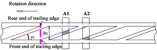
The blade outlet gradually staggered from shroud to hub in circumferential direction is defined as leaned blade. When using it, each blade in PAT no longer sweeps across the tongue at one time, but gradually over a period of time. A certain phase difference of fluid from shroud to hub is produced due to the unsteady interaction between them. Then, the in-phase pulsating hydrodynamic area is decreased, and finally the radiated noise is reduced [2].
When adopting leaned blade, the rear and front end of trailing edge on one blade will overlap with the front and rear end of adjacent blade, respectively. Three overlapping states will be presented. As adjacent blade just overlaps each other (as shown in Fig. 1), the area sweeping across the tongue remains the same. And sustained equal pulsation level can be produced, which further reduces in-phase hydrodynamic action. At this time, the adjacent blades are completely overlapped, which means the rear and front end of trailing edge is always in perfect overlapping state with the front and rear end of adjacent blade (i.e., ). The following formula exists:
The ideal circumferential leaned angle of blade can be deduced as:
where, is the impeller outlet diameter, is the impeller outlet width, is blade number, is the circumferential leaned angle of blade in ideal state. Smaller will improve the noise performance and lower the hydraulic performance. As can be seen from Eq. (2), the ideal leaned angle of blade is inversely proportional to outlet diameter, but proportional to outlet width and blade number.
Fig. 1Leaned blade in overlapping state
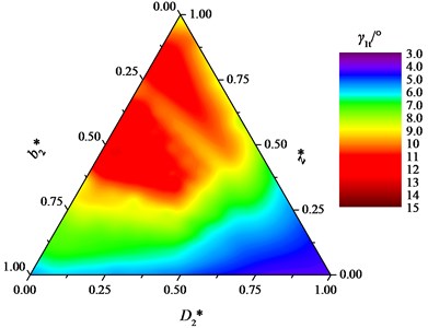
For low specific speed centrifugal pump in turbine mode, the ideal leaned angle of blade is smaller due to low ratio of outlet width to diameter (). Fig. 2 shows the relationship between the ideal leaned angle and geometric parameters inferred by Eq. (2). In which, ranges from 215 mm to 255 mm, ranges from 11 mm to 15 mm, and ranges from 5 to 12. And, these parameters are normalized. It can be seen, within certain geometric parameters, the ideal leaned angle is relatively small, with a maximum angle of 14.95°. In the range of [0, 1], [0, 0.625] and [0.5, 1], the ideal leaned angle is larger. Under the combination of 255 mm, 14 mm and 12, 11.84° can completely meet the overlapping requirement.
Fig. 2Relation between ideal leaned angle of blade and geometric parameters
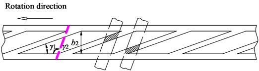
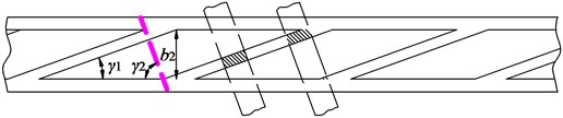
The hydraulic performance of PAT will be seriously deteriorated if is too small. So, maybe the blade and tongue can pay their leaning share. That is, apart from leaning blade, the tongue of volute is also changed from common flat to leaned type. Different leaning ways of blade and tongue are shown in Fig. 3.
Fig. 3Different leaning ways of blade and tongue
a) Parallel-leaning
b) Counter-leaning
For parallel-leaned blade and tongue in ideal state, the following formula exists:
For counter-leaned blade and tongue in ideal state, the following formula exists:
where, denotes the circumferential leaned angle of tongue in ideal state. Similarly, smaller will improve the noise performance and lower the hydraulic performance. From Eqs. (1), (3) and (4), compared to other PATs with counter-leaned blade and tongue and flat tongue, the ideal leaned angle of blade under parallel leaning state increases, which decreases the noise performance. For counter-leaning state, under the parameter combination of 255 mm, 14 mm and 12, 11.84°, 12.5° can meet complete overlapping requirement. But due to the processing limits, the ideal leaned angle of tongue cannot be made too small.
3. Numerical calculation of interior/exterior noise in PAT
A conventional PAT and its modified models whose width-diameter ratio is 0.055 are comparatively investigated. The difference between the original and modified PATs is just leaning impeller and volute or not, while other parameters remain the same. The design parameters in turbine mode are: flow rate 90 m3/h, head 35 m, rotating speed 1500 r/min and specific speed 60. The main geometric parameters are: impeller inlet diameter 102 mm, impeller outlet diameter 255 mm, impeller outlet width 14 mm, inlet blade angle 19.5°, outlet blade angle 20°, blade number 6, volute base circle diameter 266mm, volute outlet width 26 mm and volute outlet diameter 65 mm. The first and second type of modification is carried out by leaning blade 75.5° and 44° respectively. The third type of modification is leaning tongue 68°. And the final modification is realized by jointly leaning blade 44° and tongue 68°. The leaned impeller and volute used in modified PATs are shown in Fig. 4. The modified PATs are named M1, M2, M3 and M4, respectively.
Fig. 4Leaned impeller and volute used in modified PATs
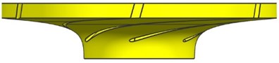
a) 75.5° leaned blade
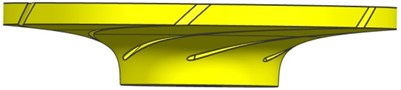
b) 44° leaned blade
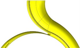
c) 68° leaned tongue
3.1. Flow and modal calculation
The fluid domain in whole flow passages, including the volute, impeller, front and back chambers, inlet pipe and draft tube, was modeled. Considering the complexity of geometry, unstructured tetrahedral elements were adopted to discrete the computational region. A grid independence test was performed. It was found when the element number was around 2.6×10⁶, the variation of efficiency was within 0.5 %. The final mesh number of three PATs was over 2.6×10⁶. To distinguish unsteady messages from internal flow, the time step was set to 1.1111×10⁻⁴ s, which means the impeller rotates about 1° in each time step [17]. After the flow changes in a stable periodic mode, the temporal pressure fluctuations on internal wall surfaces using - model were output. Four cycles of pressure fluctuations, that is, the sampling time 0.16 s, were saved for the following noise calculation.
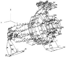
The casing structure used for noise calculation due to structural vibration consists of pump body, cover, suspension, supporting feet, inlet pipe and draft tube. When modeling, it only retains the structures with larger normal radiation area. The other tiny structures, such as the bosses, transition fillets, were removed. Moreover, the holes in structure surface, such as holes for injection and drainage and cover surface, were filled. Solid 187 was used for modal analysis, and the number of elements was 1 914 480. The Gray Cast HT200 was applied, whose density 7200 kg/m3, elastic module 148 GPa and Poisson ratio 0.3.
3.2. Noise calculation
Based on wave equation, Boundary Element Method (BEM) and Finite Element Method (FEM) can accurately solve various noise problems in low and medium frequencies. However, due to various media’s characteristics between internal water and external air, it is inadvisable to simultaneously solve interior/exterior noise through BEM, which can only be set one fluid material. At present, the interior noise caused by rotating dipole source of impeller can only be solved by BEM. And, it is more effective in dealing with exterior noise problems in unbounded physical domain using FEM. Therefore, BEM was used to solve interior noise, and exterior noise was calculated by FEM.
As major noise source, the dipole source can roughly be excited by rotating impeller and fixed casing. For the interior noise generated by casing source, firstly four cycles of pressure fluctuations on inner walls of casing were output. Then, the closed acoustic field can be solved with the pressure fluctuations set as acoustic boundary condition transformed by Fast Fourier Transform (FFT). As for the interior noise due to impeller’s rotation, only excitation in time domain was needed to be extracted without FFT. To make compact compared with acoustic wavelength, the impeller was divided into 10 pieces. To simulate the direct propagation of noise in piping without reflection, the inlet pipe and draft tube were set to full absorption, and other surfaces were defined as total reflection, with the acoustic impedance 1.5×10⁶ kg/(m2∙s). Monitoring point was set at the same position with the experiment.
For exterior noise calculation, firstly the pressure fluctuations were transferred to inner walls of casing structure. Then, the vibration response was solved based on structure modal. Finally, with the vibration displacement on inner walls as boundary condition, exterior noise was solved. During the calculation, the internal boundary of finite element mesh fitted well with the casing shape. And, the external boundary was established as convex with AML attribute specified. Fig. 5 shows the acoustic boundary conditions for noise calculation.
Fig. 5Acoustic boundary conditions for noise calculation
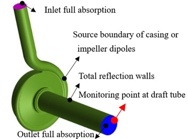
a) Interior noise
b) Exterior noise
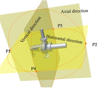
Due to obvious directivity of sound transmission, the measured sound pressure level (SPL) is not the same at different locations with respect to sound sources in space. To obtain the distribution of SPL, the impeller rotating center (0, 0, 0) was regarded as the origin to establish monitoring planes of 1 m×1 m respectively paralleling to , , . These planes were defined as horizontal, vertical, and axial direction. 36 monitoring points were disposed on each monitoring plane at 1 m away from the center of impeller, and the angle between each point was 10°, as shown in Fig. 6. The four monitoring points were established to monitor the frequency response curves of exterior noise.
Fig. 6Monitoring planes and points
4. Experimental verification
4.1. Hydraulic performance and interior noise
The experimental measurements of hydraulic performance and interior noise were carried out, as shown in Fig. 7. Derakhshan [18] established a correlation between the performances of direct (pump) and reverse (turbine) modes. To measure the turbine’s shaft torque, the generator was modified to suspense state mode. Bozorgi [19] built a test bench for axial pump as turbine using similar method. In their testing systems, the energy recovered by PAT was measured by the energy conversion way from pressure energy to electric energy. There are two main demerits: (1) because the motor’s speed cannot be maintained constant only by the load controller, and the flow and head of output load need to be adjusted, the output energy of PAT is not stable; (2) the flow only adjusted through regulating valve makes the flow not easy to control. Singh [20] added a surge tank in his test to make the head of inlet constant and adjust flow. However, the test bench is difficult to establish with complex pipelines and high cost.
Fig. 7Sketch of the test ring
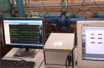
To cure the above problems, the PAT was connected with dynamometer in the paper. A CWF22L eddy current dynamometer was used to consume and measure the energy recovered by PAT. The impeller of PAT was rotated due to the impact of high pressure water supplied from the booster pump. In the control mode of constant speed, the EST measuring and control system can make the speed of PAT remain constant over time. The discharge and pressure of inlet and outlet were respectively measured by flow meter and pressure transmitter. The uncertainty of measured parameters, such as head , flow rate , hydraulic power , shaft power and efficiency were ±0.14 %, ±0.50 %, ±0.52 %, ±1.08 % and ±1.20 %, respectively. The INV vibration and noise test system from China Orient Institute of Noise and Vibration was used to acquire noise signals. The system included INV3020C high-performance 24-position acquisition system and DASP large-capacity data processing software. A ST70 hydrophone was flush mounted on the piping, which was four times of outlet diameter away in turbine mode. In the process of measuring under each flow rate, the valves remained fully opened, eliminating the influence of valve noise in pipeline. The data acquisition frequency was chosen equal to 25.6 kHz per channel with a resolution of 12.5 Hz. To reduce random noise error, the spectrums of four divided pieces of data were averaged using the whole average method. Besides that, to reduce leakage error in frequency-domain due to time domain truncation, Hanning window was adopted to process data.
The conventional PAT was selected for validation of calculation accuracy. Fig. 8 shows a comparison of hydraulic performance curves between calculation and experiment. We can see, the tendency of calculated curves is in agreement with that of experiment, especially in larger flow rate. The numerical efficiency, head, and shaft power are lower for part-load conditions than experimental results, with a largest difference of 8.44 % at 70 m3/h. The comparison indicates the mesh and turbulence model are suitable for hydraulic performance prediction.
Fig. 8Comparison of hydraulic performance between calculation and experiment
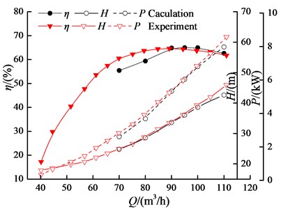
Fig. 9 shows a comparison of spectrum curves of interior noise between calculation and experiment under three flow conditions. It is found that the calculated spectrum curves obtained from both impeller and casing dipole sources are in good agreement with experimental results, especially in optimal and large flow condition. In the range of 12.5 Hz to 450 Hz, the SPL at a given frequency obtained from experiment is higher than calculated value on the whole. The calculated SPL at dominant frequency is basically identical with experimental value, while larger differences exist among low frequencies. Within the range of 450 Hz to 2000 Hz, the calculated broadband spectrum agrees well with the experiment, while larger SPL deviation exists at Blade-Passing Frequency (BPF) and its harmonics.
According to sound energy superposition principle, the noise under the action of two sound sources is determined by the sound source with higher SPL. At shaft frequency, the final noise is determined by impeller source, with minimum error of 12.6 %. At BPF and its harmonics, the final noise is basically determined by casing source, with relatively smaller errors in optimal and large flow conditions. During these flow conditions, the biggest error is 9.3 %, the minimum error is –0.9 %, and the average error is only 4.35 %. It can be inferred that, the interior noise due to casing source can reflect joint action of multiple sources. And, it is feasible to predict interior noise induced only by casing source through BEM. The causes of error are analyzed as below:
(1) In the process of measurement, the impeller is unlikely completely dynamically balanced. Certain levels of vibration will be generated at the hydrophone installed on draft tube, lowering measurement accuracy. (2) The actual noise excited by unsteady flow will radiate inside after repeated reflection and scatter on irregular walls. The scattering effect is ignored during noise calculation. So, the interior noise may be enhanced at some frequencies, and suppressed at others. (3) The internal flow of PAT is complex at smaller flow rates, including flow separation, backflow, and so on. Only the hydrodynamic noise based on URANS was calculated, so the calculated value may be less.
Fig. 9Comparison of spectrum curves between calculation and experiment
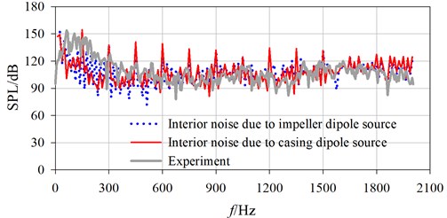
a) 80 m3/h
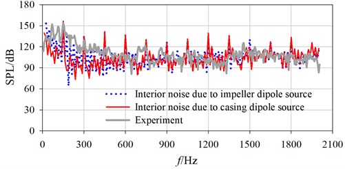
b) 90 m3/h
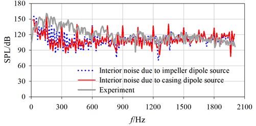
c) 110 m3/h
4.2. Structure modal used for exterior noise
The modal test of casing was performed by moving incentive points with a single response point fixed. The acceleration transducer and force-hammer were connected to signal modulation system and SD380 dynamic analysis system. Then the matrix of frequency response function (FRF) for free system was constructed. At last, the modal parameters were extracted from the FRF matrix by polynomial curve fitting techniques in frequency domain. The acquisition frequency was chosen equal to 5.12 kHz with a resolution of 6.4 Hz. The transient force window was imposed to improve the signal-to-noise ratio of excitation signal. And index window was imposed on response signal to accelerate vibration attenuation and avoid leakage of frequency response function. Table 1 gives the first seven modal frequencies in free condition. And, Fig. 10 shows three representative modes of vibration. As can be seen, the modes of vibration are approximate between calculation and experiment. The calculated errors of modal frequencies are within 7 %, meaning the finite element model is available for noise analysis based on modal.
In practice, the PAT is fixed on ground by bolts, and the inlet and outlet are connected with inlet pipe and draft tube. So the boundary conditions of modal analysis were set as: the bottom contacted with ground was supposed six constraints, the up and down displacement was restricted on inlet pipe, and the axial displacement was restricted on draft tube. The constraint natural frequencies are 311.10 Hz, 416.83 Hz, 762.87 Hz, 886.73 Hz, 1363.75 Hz, 1603.67 Hz and 1715.77 Hz, respectively.
Table 1Comparison of free modal frequency between calculation and experiment
Model | Order | Frequency / Hz | Error / % | Damping ratio / % | |
Experiment | Calculation | ||||
Casing | 1 | 285.62 | 265.84 | -6.93 | 1.62 |
2 | 618.65 | 638.84 | 3.26 | 0.70 | |
3 | 864.23 | 875.59 | 1.31 | 0.30 | |
4 | 1010.0 | 946.66 | -6.27 | 0.68 | |
5 | 1050.0 | 1073.9 | 2.28 | 0.28 | |
6 | 1110.0 | 1194 | 7.57 | 0.26 | |
Fig. 10Comparison of free mode of vibration between calculation and experiment
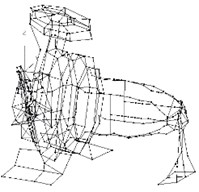
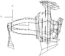
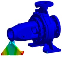
a) Second-order
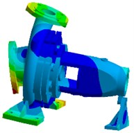
b) Third-order
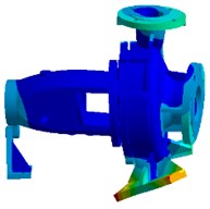
c) Sixth-order
5. Results and discussions
5.1. Influence of leaning blade or tongue on hydraulic performance
The hydraulic performance curves of PATs were obtained by numerical calculation, as shown in Fig. 11. Table 2 lists the corresponding Best Efficiency Points (BEP). From Fig. 11, after leaning blades, the efficiency of the PAT at most flow rates declines slightly with a biggest drop of 0.6 %. Whereas at larger flow rates (90 m3/h), the efficiency increases, reaching a maximum increase of 0.15 % observed at the largest flow rate 110 m3/h. In addition, along with enlarging blade’s leaning angle, its amplitude of increase improves at larger flow rates. Compared with conventional PAT, the efficiency of the PAT with a leaned tongue increases over full flow rates. And, the increase is from 0.67 % to 1.81 % with a relative smaller increase after BEP than before. After counter-leaning blade and tongue, the efficiency is basically same with conventional PAT. But there is a certain increase of efficiency at larger flow rates. Table 3 shows that as the angle is leaned by 75.5° and 44°, the flow rate at BEP is increased by 10 m3/h and 5 m3/h, respectively. This indicates that there is a rise of flow rate at BEP with the inclination of blade. Additionally, we can see there is a rise of flow rate at BEP for leaned tongue or combined with leaned blade. All these indicate that the leaned blade can keep PAT’s original performance, the leaned tongue can significantly improve PAT’s efficiency over an overall flow range, and the combined leaned blade and volute can increase the efficiency in larger flow rates.
Fig. 11Comparison of hydraulic performance curves
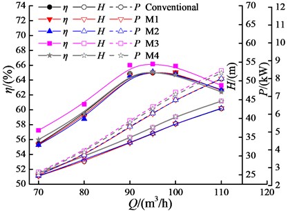
Table 2PAT’s BEPs with different blade and tongue
Models | (m3/h) | (m) | (kW) | (%) |
Conventional | 90.00 | 38.59 | 6.81 | 64.98 |
M1 | 100.00 | 38.59 | 6.82 | 65.05 |
M2 | 95.00 | 35.98 | 6.05 | 65.13 |
M3 | 95.00 | 37.58 | 6.42 | 66.16 |
M4 | 95.00 | 37.61 | 6.32 | 65.09 |
5.2. Influence of leaning blade or tongue on interior/exterior noise
Fig. 12 shows the comparison of SPLs at discrete frequencies in interior noise for 90 m3/h. When the blade and tongue are leaned, the SPLs at BPF and its second-order and fifth-order frequencies increase firstly and then decrease. At these frequencies, the SPLs under joint action of leaned blade and tongue are reduced by about 2.48 dB, 4.08 dB and 2.57 dB. Whereas, by leaning blade 44°, the SPLs increase 0.39 dB, 1.69 dB and 0.4 dB. Of course, at some other frequencies, the SPLs are reduced by leaning blade. For example, there is a noise reduction of 1.76 dB at 450 Hz.
Fig. 12Comparison of SPLs in interior noise, Q= 90 m3/h
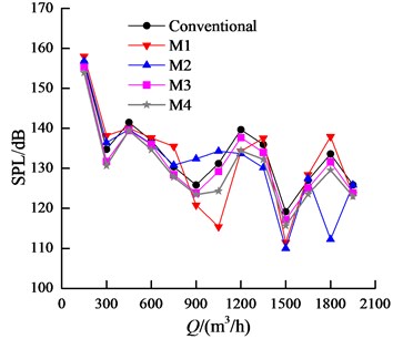
Fig. 13 shows the comparison of spectrum curves in exterior noise for conventional PAT at four monitoring points generated by casing dipole for 90 m3/h. The peak value occurs at fifth-order BPF followed by second order BPF, mainly because they are close to the third and first constraint natural frequency of casing. It indicates the exterior noise is determined both by internal fluid and solid structure.
Due to approximate directivity on three monitoring planes for exterior noise, the horizontal directivity was analyzed here focusing on fifth-order BPF. Fig. 14 gives the sound pressure distribution under three typical working conditions. At the fifth-order BPF, the space directivity of modified PATs is nearly the same compared with conventional PAT, showing a side lobe phenomenon. At all flow rates, the exterior noise decreases for leaned blade 44°, while increases for leaned blade 75.5°. Respectively for leaned blade 44° and 75.5°, the noise reduces by 2.84 dB and increases by 0.76 dB at 80 m3/h, and 2.97 dB and 0.91 dB at 110 m3/h. At 80 m3/h, the noise is reduced by 5.00 dB and 5.12 dB, respectively for leaned tongue or joint leaned blade and tongue. At 90 m3/h and 110 m3/h, the noise reduction effect is better for joint action. The noise reduction is approximately 3.68 dB and 5.76 dB for the two flow rates.
Fig. 13Comparison of SPLs in exterior noise for conventional PAT, Q= 90 m3/h
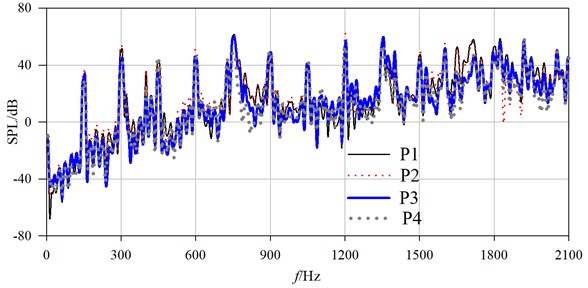
Fig. 14Comparison of directivity distribution at fifth-order BPF in exterior noise

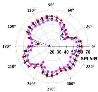
a) 80 m3/h
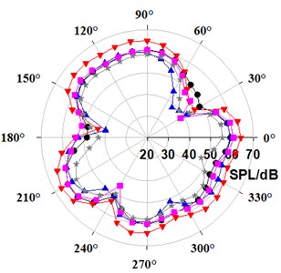
b) 90 m3/h
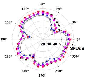
c) 110 m3/h
The overall interior/exterior noise characteristics were compared, as shown in Table 3. The interior noise was evaluated by overall sound pressure level. The exterior noise was estimated by overall sound power level. Sound power level is used to characterize the amount of radiation energy from sound source, independent of propagation distance of sound wave and environment. On the basis of reference pressure in air, the A-weighted was applied within the frequency range from 12.5 Hz to 2000 Hz, because of its closer feeling to human’s ears. At the same flow rate, the interior/exterior noise of PATs with leaned blade or tongue reduces greatly, and the decreasing amplitude under the combined effect of leaned blade and tongue is basically greatest. The overall sound pressure level under the combined effect reduces 7.19 %, and the overall sound power level decreases 12.15 % at the largest flow rate 110 m3/h. The noise reduction effect is nearly the same for only leaning blade 44° or leaning tongue 68° at all flow rates. The highest decreasing amplitude can be observed at the largest flow rate 110 m3/h for all modified PATs, and the smallest decreasing amplitude has been obtained for 80 m3/h. As can be seen, the peak value at fundamental frequency can be reduced by leaned blade or tongue. In addition, the leaned blade or tongue can reduce the total sound energy in full-frequency band. Considering both the hydraulic and noise performance, the comprehensive performance of PAT under the combination of leaned blade and tongue is optimal.
Table 3Interior/exterior noise characteristics of PATs with different blade and tongue
(m3/h) | Models | Overall sound pressure level (dBA) | Overall sound power level (dBA) |
80 | Conventional | 146.74 | 67.64 |
M1 | 142.90 | 67.55 | |
M2 | 142.31 | 66.75 | |
M3 | 141.07 | 67.08 | |
M4 | 140.21 | 66.91 | |
90 | Conventional | 152.50 | 72.46 |
M1 | 146.28 | 68.86 | |
M2 | 144.61 | 67.75 | |
M3 | 143.46 | 68.38 | |
M4 | 142.95 | 65.97 | |
110 | Conventional | 154.57 | 77.18 |
M1 | 147.25 | 69.57 | |
M2 | 145.90 | 67.94 | |
M3 | 145.55 | 68.43 | |
M4 | 143.46 | 67.80 |
5.3. Influence of leaning blade or tongue on hydraulic exciting force
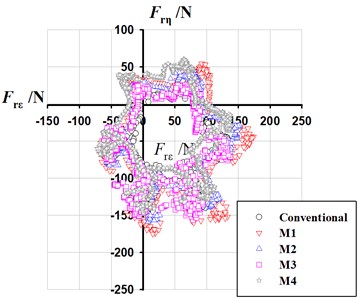
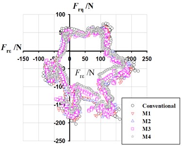
The hydraulic exciting force acting on structure surface is the direct reason causing interior noise. Fig. 15 shows the vector diagrams of radial exciting force on impeller in rotating coordinate system.
In terms of the distribution of radial force, it still shows a hexagonal distribution after leaning blade or tongue. In terms of the value of radial force, it decreases to some extent. At 80 m3/h, the leaned tongue only makes the radial force reduce by 0.69 % compared with conventional PAT. As the blade is leaned from 90° to 44°, the radial force decreases gradually with bigger reduction. The leaned blade with 44° makes the radial force reduce by 17.94 % compared with conventional PAT. Under the joint action of leaned blade 44° and leaned tongue 68°, the radial force is reduced by 21.53 %. As the flow rate increases, the reduction effect is more obvious by leaning blade or tongue, and the reduction is up to 40.70 % under the combined action.
Fig. 15Comparison of hydraulic exciting force
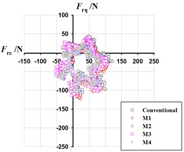
a) 80 m3/h
b) 90 m3/h
c) 110 m3/h
6. Conclusions
The active noise reduction approaches were put forward by leaning blade or tongue, and it can reduce interior/exterior noise without lowering hydraulic performance. The conclusions are as follows:
1) The calculated hydraulic performance curve of conventional PAT coincides well with the experiment, especially at larger flow rate. At BPF and its harmonics, the interior noise is basically determined by casing source with relatively smaller errors at optimal and larger flow rates. The interior noise due to casing source can reflect joint action of multiple sources. The modes of vibration are approximate between calculation and experiment, indicating the finite element model of casing structure is suitable for exterior noise analysis based on modal.
2) The efficiency of the PATs by leaning blades declines at most flow rates, with a slight increases at larger flow rates. After a certain inclination of tongue, the efficiency increases over full flow rates. After counter-leaning blade and tongue, the efficiency remains basically the same with conventional PAT. The SPL at each discrete frequency in interior/exterior noise and radial exciting force acting on structure surface can be reduced by simply leaning blade or tongue and joint leaning blade and tongue. And they can reduce the total sound energy in full-frequency band. Considering both hydraulic and noise performance, the comprehensive performance of PAT under the joint action is optimal.
References
-
Nautiyal H., Anoop Kumar V. Reverse running pumps analytical, experimental and computational study: a review. Renewable and Sustainable Energy Reviews, Vol. 14, Issue 7, 2010, p. 2059-2067.
-
Lu F. A. Numerical and Experimental Study on the Flow-Induced Vibroacoustics of a Centrifugal Fan and Compressor. Xi’an Jiaotong University, Xi’an, 2014.
-
Tourret J., Badie-Cassagnet A., Bernard G., et al. Experimental studies of noise emission and noise generation from a centrifugal pump. ASME Paper No. 95-WA/FE-8, 1985.
-
Dong R., Chu S., Katz J. Effect of modification to tongue and impeller geometry on unsteady flow, pressure fluctuations, and noise in a centrifugal pump. Journal of Turbomachinery, Vol. 119, Issue 3, 1997, p. 506-515.
-
Langthjem M. A., Olhoff N. A numerical study of flow-induced noise in a two-dimensional centrifugal pump. Part I. Hydrodynamics. Journal of Fluids and Structures, Vol. 19, Issue 3, 2004, p. 349-368.
-
Langthjem M. A., Olhoff N. A numerical study of flow-induced noise in a two-dimensional centrifugal pump. Part II. Hydroacoustics. Journal of Fluids and Structures, Vol. 19, Issue 3, 2004, p. 369-386.
-
Neise W. Noise reduction in centrifugal fans: a literature survey. Journal of Sound and Vibration, Vol. 45, Issue 3, 1976, p. 375-403.
-
Yang S. S., Kong F. Y., Shao F., et al. Numerical simulation and comparison of pump and pump as turbine. ASME 2010 3rd Joint US-European Fluids Engineering Summer Meeting collocated with 8th International Conference on Nanochannels, Microchannels, and Minichannels, Montreal, Quebec, Canada, 2010.
-
Derakhshan S., Nourbakhsh A. Theoretical, numerical and experimental investigation of centrifugal pumps in reverse operation. Experimental Thermal and Fluid Science, Vol. 32, Issue 8, 2008, p. 1620-1627.
-
Singh P., Nestmann F. An optimization routine on a prediction and selection model for the turbine operation of centrifugal pumps. Experimental Thermal and Fluid Science, Vol. 34, Issue 2, 2010, p. 152-164.
-
Yang S. S., Kong F. Y., Chen H., et al. Effects of blade wrap angle influencing a pump as turbine. Journal of Fluids Engineering, Vol. 134, Issue 6, 2012, p. 061102.
-
Yang S. S., Kong F. Y., Jiang W. M., et al. Effects of impeller trimming influencing pump as turbine. Computers and Fluids, Vol. 67, 2012, p. 72-78.
-
Yang S. S., Kong F. Y., Fu J. H., et al. Numerical research on effects of splitter blades to the influence of pump as turbine. International Journal of Rotating Machinery, 2012, p. 123093.
-
Dai C., Kong F. Y., Dong L., et al. Effect of blade wrap angle on the radial force of centrifugal pump as turbine. Journal of Vibration and Shock, Vol. 34, Issue 18, 2015, p. 69-99.
-
Dai C., Kong F. Y., Dong L., et al. Hydraulic and acoustic property optimization for centrifugal pump as turbine based on response surface method. Transactions of the Chinese Society of Agricultural Engineering, Vol. 31, Issue 15, 2015, p. 40-47.
-
Dong L., Dai C., Kong F. Y., et al. Impact of blade outlet angle on acoustic of centrifugal pump as turbine. Transactions of the Chinese Society of Agricultural Engineering, Vol. 31, Issue 6, 2015, p. 69-75.
-
Dai C., Kong F. Y., Dong L. Pressure fluctuation and its influencing factor analysis in circulating water pump. Journal of Central South University, Vol. 20, Issue 1, 2013, p. 149-155.
-
Derakhshan S., Nourbakhsh A. Experimental study of characteristic curves of centrifugal pumps working as turbines in different specific speeds. Experimental Thermal and Fluid Science, Vol. 32, Issue 3, 2008, p. 800-807.
-
Bozorgi A., Javidpour E., Riasi A., et al. Numerical and experimental study of using axial pump as turbine in Pico hydropower plants. Renewable Energy, Vol. 53, 2013, p. 258-264.
-
Singh P. Optimization of the Internal Hydraulic and of System Design in Pumps as Turbines with Field Implementation and Evaluation. University of Karlsruhe, Karlsruhe, 2005.
About this article

This work was supported by National Natural Science Foundation of China (Nos. 51509111, 51309119), China Postdoctoral Science Foundation (2015M581734), the Advanced Talent Foundation of Jiangsu University (12JDG082, 15JDG052), the Open Research Subject of Key Laboratory of Fluid and Power Machinery, Ministry of Education, Xihua University (szjj2015-017), Sichuan Provincial Key Lab of Process Equipment and Control (GK201403), Major Science and Technology Projects of Zhejiang Province (2014C01004-1) and a Project funded by the Priority Academic Program Development of Jiangsu Higher Education Institutions (PAPD).
