Abstract
A brand-new smart wind turbine blade with magnetorheological fluid (MRF) sandwiched was proposed in the research. The three-dimension entity model of a 750 KW wind turbine blades was established through the use of UG software, and three kinds of MRF sandwich layouts were considered into the blade model, that is, at the blade tip, at the blade root and at the whole blade from the root till the tip. The MRF was simplified as Kelvin-Voigt model in order to implement the finite element analysis based on ANSYS software, so that the mode shapes of smart wind turbine blade were revealed under various conditions with three different layout forms of MRF sandwich wind turbine blades. Analysis results showed that the magnetic field would influence the mode shapes of the wind turbine blade with MRF sandwiched, especially the torsion vibration. When the MRF was inserted through the blade from the root till the tip, the blade would dramatically influence the torsion vibration, so that the torsion vibration, which originally would have happened at higher orders, would arise in advance. While the MRF was located at the root of wind turbine blade, the torsion vibration would be postponed to arise at the higher orders. Therefore, the MRF should be located at the blade root, instead of the middle and the tip of wind turbine blade. Smart sandwich wind turbine blade will provide a new way to the vibration control of wind turbine blade.
1. Introduction
As energy and environment has been drawn attention greatly recently, the development of new energy and renewable energy has been promoting rapidly. Wind energy, as a renewable energy representative, has also been greatly developed in the world. As a key component of wind energy, wind turbine blades play a key role for the safe and stable operation and its size scale is also growing larger and larger. In order to meet the requirements of different conditions of wind power, smart wind turbine blades are becoming one of the hottest aspect of wind power, and will represent the development direction of the wind turbine blade.
As early as 2001, Sundaresan M. J. proposed a conceptual “smart wind turbine blade”, the blade integrated active and passive piezoelectric sensor systems that could monitor wind turbine status and predict alarm in advance [1]. Barlas T. K. pointed that wind turbine blades “embedded smart structures” would reduce the wind wheel load effectively, and significantly reduce the total cost of the wind turbine [2, 3]. Nelson R.C. proposed a new intelligent wind turbine blades which integrates the sensors, actuators and controllers together, which could capture much more wind energy and reduce the aerodynamic loads and wind turbine noise [4]. Barlas T. K. pointed that smart material actuators occupied a very important position in the smart wind turbine blade, the actuator must store distributedly and response rapidly. Piezoelectric actuators had been applied in wind tunnel tests of scaling intelligent wind turbine blade model. As typically smart materials, piezoelectric materials, shape memory alloys and the electrorheological materials and magnetorheological materials, will play an active role in the smart wind turbine blades actuator in the future [5].
In recent years, electrorheological and magnetorheological materials can quickly modify the rheological properties when applying the electric field or magnetic field, it has received attention from many fields, but current study focused mostly on a simple sandwich plate or beam structure. Rahn C. D. established dynamic model of electrorheological sandwich cantilever beam, and analyzed the inhibition of ER fluid material to sandwich beam vibration based on the viscoelastic theory [6]. Choi S. B. has carried on the theoretical and experimental research for the dynamic characteristics of electrorheological fluid sandwich beam [7]. Gong H. carried out experimental research on electrorheological fluid sandwich beam, in order to study factors sandwich beam natural frequency and damping loss factor [8].
More and more people paid more attention to the magnetorheological fluid, mainly in intelligent sandwich plate structure. Q. Sun analyzed the adaptive beam containing magnetorheological materials, and studied the vibration characteristics under different magnetic fields [9]. Hu B. X. established a finite element model of MRF sandwich simply supported beam, and verified the natural frequencies and loss factors beams would increase with increasing magnetic field strength increasing [10]. Rajamohan V. studied dynamics problem of three-layer sandwich structure that the intermediate layer was a magneto-rheological fluid and both outside layers were elastic structure layer, discussed the changes of natural frequencies and loss factor of sandwich beam [11]. Yalcintas M. studied the dynamic characteristics of the MRF sandwich simply supported beam based on the energy method, the MRF sandwich beam would suppress vibration under an applied magnetic field [12].
Although there are many researches on smart materials and smart sandwich, however there are few for applying the smart materials into the intelligent blades of the wind turbine blades. Qiao Y. H. studied the modeling problems of intelligent wind turbine blades with embedded piezoelectric material [13].
This paper presented a new type of intelligent sandwich wind turbine blades, which magnetorheological fluid were inserted in wind turbine blades as the wind turbine blade sandwich. Under different magneto-rheological fluid layouts in blade and various working conditions, the finite element analysis would be carried out to study on the vibration characteristics of a wind turbine blade with MRF sandwiched.
The paper is organized as follows: three-dimensional model of wind turbine blade, different layouts of magnetorheological sandwich in the blade, the finite element model of MRF sandwich blade, the blade working conditions of wind turbine blade, blade vibration modal analysis under different MRF sandwich layouts and different working conditions.
2. Three-dimension model of wind turbine blade
2.1. The geometric features and parameters of the wind turbine blade
In order to highlight the role of magnetorheological sandwich and reduce the complexity of the problem, we establish three-dimension blade using entity model instead of complex hollow wind turbine blade.
Table 1Part of the section parameters of 750 KW horizontal axis wind turbine blade
Section | Radius / (m) | Airfoil | Tip speed ratio | Chord length / (m) | Torsion angle / (°) |
1 | 4.84 | NACA4412 | 1.2 | 4.18 | 19.72 |
3 | 7.26 | NACA4412 | 1.8 | 3.39 | 12.89 |
6 | 10.89 | NACA4412 | 2.7 | 2.42 | 7.27 |
9 | 14.52 | NACA4412 | 3.6 | 1.9 | 4.1 |
12 | 18.15 | NACA4412 | 4.5 | 1.59 | 4.5 |
15 | 21.78 | NACA4412 | 5.4 | 1.52 | 0.24 |
17 | 24 | NACA4412 | 6 | 1.55 | 0.65 |
In this paper, 46 m in diameter and the maximal tip ratio 6 of a 750 KW horizontal axis wind turbine blade is considered as object. The airfoil model is NACA4412. The maximal relative camber is 4 % and maximal relative thickness is 12.2 %, which locate at the chord length of 40.9 % and 29.8 %, respectively.
According to blade element momentum theory, the blade along spanwise is divided into 16 segments, a total of 17 section, the radius, tip speed ratio, chord length, torsion angles of section 1, 3, 6, 9, 12, 15, 17 are shown in Table 1 [14].
2.2. The actual coordinate of each blade section
For simple modeling, a three-dimension coordinate system was created, using aerodynamic center of blade root element plane as the origin of coordinates, the element plane of blade root as plane and spanwise direction as positive direction of axis. The actual coordinates of each discrete point of blade element can be obtained through the following steps:
(1) Get the original date of NACA4412 airfoil by Profili software.
(2) Assume the coordinates of the aerodynamic center is , the 2-dimension coordinates can be solved as Eq. (1), the aerodynamic center was the origin and the connection of leading edge and trailing edge was axis:
(3) Solve the actual coordinates of discrete points of the blade element space Calculate coordinates of each blade element based on chord length according to Eq. (2):
where, is chord length.
Actual space coordinates will be acquired according to Eq. (3), by rotating blade element:
where, is local radius, is torsion angle of each section of wind turbine blade.
2.3. The three-dimension of wind turbine blade
The three-dimension model of wind turbine blade is shown as Fig. 1.
3. Different layouts of magnetorheological sandwich in the blade
The shape of MRF sandwich is considered as rectangle thin layer, the reasons are as following:
(1) There are torsion among different cross sections of wind turbine blade.
(2) The torsion of the MRF sandwich will not be considered.
(3) The MRF sandwich is easy to implement, and will not affect the structure of the whole blade.
In the running process of wind turbine blade, the largest part of vibration displacement is the tip and the largest part of load bearing is the blade root, therefore, we can layout MRF sandwich at the two typical sites, whose local amplification figures are shown in Fig. 2(a) and Fig. 2(b). In addition, to compare with the characteristics of wind turbine blade which are arranged with MRF sandwich above, the third layout form of MRF is along the edge from the root to the tip (Fig. 2(c)). Because of the blade structure, the size of the MRF sandwich are not the same for the three conditions, the MRF sandwich size of blade root is larger, and the MRF sandwich of the tip and the overall layout is relatively smaller. The finite element analysis will be conducted for the wind turbine blade according to the three kinds of layouts of MRF sandwich.
Fig. 1The three-dimension model of wind turbine blade
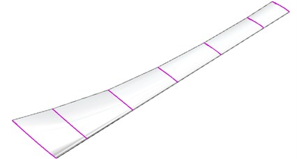
Fig. 2The MRF sandwich
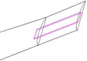
a) The MRF sandwich is located at the blade tip
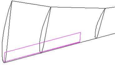
b) The MRF sandwich is located at the blade root
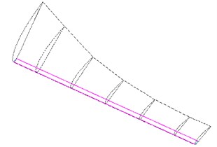
c) The MRF sandwich is located at the whole blade
4. The finite model of the MRF sandwich blade
The three-dimensional entity model of smart wind turbine blades with different MRF layout are imported into ANSYS. Using free mesh and choosing intelligent size control, the wind turbine blade with MRF sandwich is generated mesh.
As an example, Fig. 3 gives the mesh of the blade which the MRF sandwich is located at the blade tip.
4.1. Define the type of unit and material properties
Wind turbine blade materials is epoxy glass fiber reinforced plastic material, its density is 1700 kg/m3, Poisson’s ratio is 0.15, the modulus of elasticity 2.2×10¹⁰ Pa.
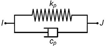
As the characteristics of MRE and difficult to describe in the finite element software, Kelvin-Voigt model is used to simulate the behavior of the MRF [15], as shown in Fig. 4. SOLID185 element is chosen as analysis element for wind turbine blades, and COMBIN40 element is chosen as analysis element for MRF sandwich. The spring stiffness and damping coefficient can be defined according to [15]. The density of MRF is 3400 kg/m3.
Fig. 3The mesh of the MRF sandwich blade
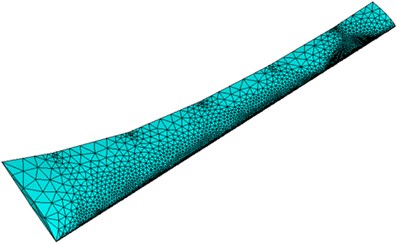
Fig. 4Kelvin-Voigt model of MRF
4.2. Impose constraints
Without considering the rotary motion, constraints to UX, UY, UZ directions can be imposed on the bottom plain of Wind turbine blade model
When considering the rotary motion, a rotating angular velocity can be applied around axis at the blade root, and constraints can be applied along the axial and circumferential direction of wind turbine blade.
5. The working conditions of wind turbine blade
The Block Lanczors method of modal analysis can be applied for the Modal analysis for the MRF sandwich blade at the tip, the root and the whole blade. The first 8 orders are determined for solving mode and extending mode. The frequency range is within 1000 Hz. The following four different working conditions for the MRF sandwich wind turbine blade are considered, respectively.
Working condition 1: The magnetic field strength is 0 Oersted and the rotating angular velocity is 0 rad/s.
Working condition 2: The magnetic field strength is 1860 Oersted and the rotating angular velocity is 0 rad/s.
Working condition 3: The magnetic field strength is 0 Oersted and the rotating angular velocity is 50 rad/s.
Working condition 4: The magnetic field strength is 1860 Oersted and the rotating angular velocity is 50 rad/s.
6. Blade vibration modal analysis under different MRF sandwich layouts and different working conditions.
Since there are three different types of MRF sandwich form and there are four different kinds of working condition under each MRF arrangement, a total of 12 kinds of circumstances will be obtained. For simplicity, this section will analyze the mode shape of wind turbine blade with three different MRF sandwich layout under the working condition 4.
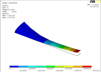
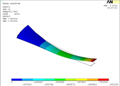
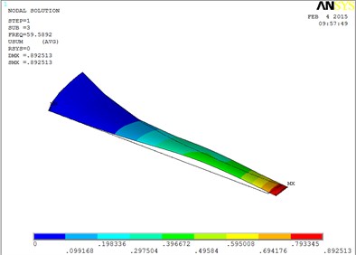
6.1. The mode shapes of blade with MRF sandwiched at the tip of blade
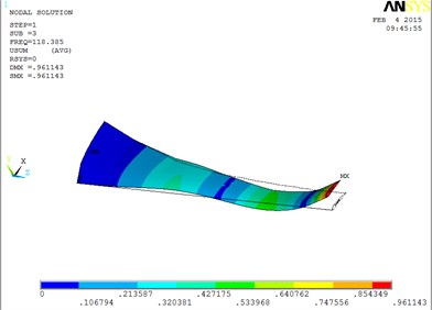
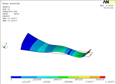
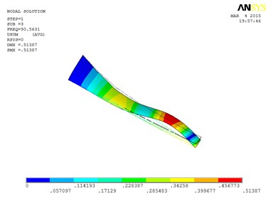
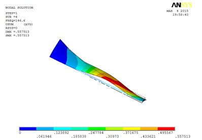
Under working condition 4, the vibration mode of the blade are shown as Fig. 5, when MRF sandwich is arranged at the tip of blade.
Fig. 5The vibration mode of the blade
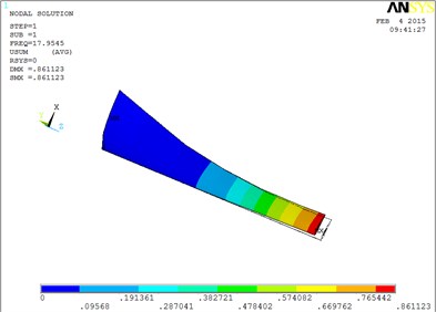
a) The first order mode shape
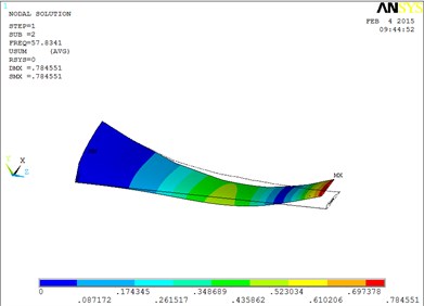
b) The second order mode shape
c) The third order mode shape
d) The fourth order mode shape
e) The fifth order mode shape
f) The sixth order mode shape
g) The seventh order mode shape
h) The eighth order mode shape
The changing trends of vibration mode shape are shown as Table 2, according to Fig. 5, the first eight orders of the vibration modal analysis of wind turbine blade which MRF is located at the tip of blade. When the MRF sandwich is located at the tip of blade, the blade vibration energy mainly concentrates on the first two orders and mainly focuses on flap motion.
Table 2Mode shapes of wind turbine blade when MRF is located at the tip of blade
Order | Mode shape | Order | Mode shape |
1 | flap | 5 | flap, lag and unobvious torsion |
2 | flap | 6 | obvious torsion |
3 | flap and lag | 7 | coupled flap-lag-torsion |
4 | flap and lag | 8 | coupled flap-lag-torsion |
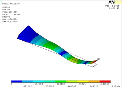
6.2. The mode shapes of blade with MRF sandwiched at the root of blade
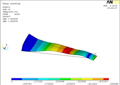
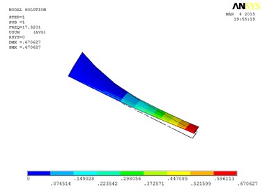
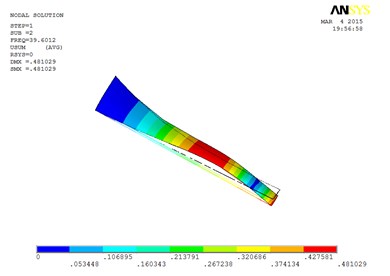
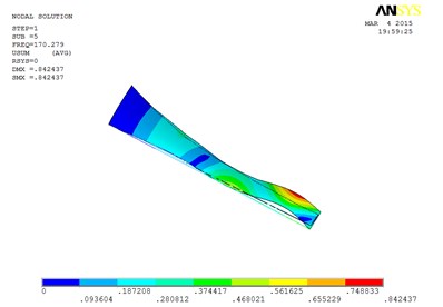
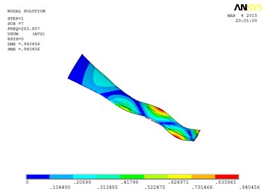
Under working condition 4, the blade mode shapes wind turbine blade with MRF sandwiched at the root of blade are shown as Fig. 6.
According to Fig. 6, the changing trends of vibration mode shape are shown as Table 3, the first eight orders of the vibration modal analysis of wind turbine blade which MRF is located at the root of blade.
The first eight orders of mode shapes look a little similar for the wind turbine blade with MRF sandwiched at the tip and at root of the blade. However, compared with the blade sandwiched at the tip, the torsion mode of the blade sandwiched at the root is postponed, the obvious torsion will arise until the seventh order of mode shape.
Table 3Mode shapes of wind turbine blade when MRF is located at the root of blade
Order | Mode shape | Order | Mode shape |
1 | Flap | 5 | Flap and lag |
2 | Flap | 6 | Flap, lag and obvious torsion |
3 | Flap and lag | 7 | Torsion |
4 | Flap and lag | 8 | Coupled flap-lag-torsion |
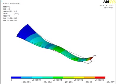
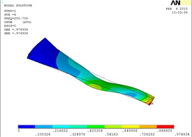
6.3. The mode shapes of blade with MRF sandwiched at the whole blade
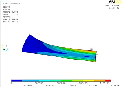
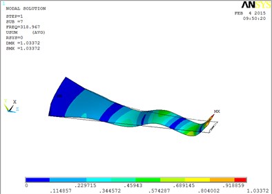
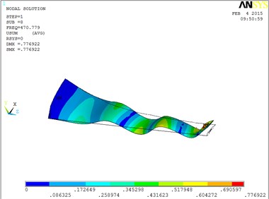
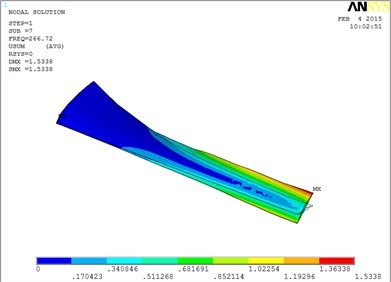
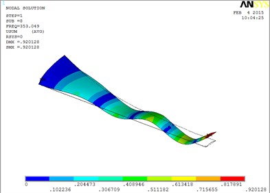
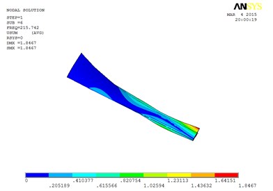
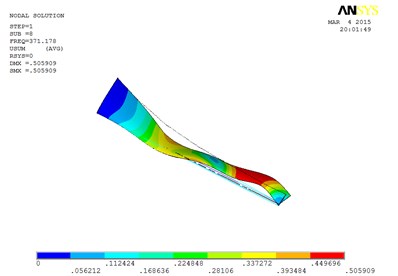
Under working condition 4, the blade mode shapes wind turbine blade with MRF sandwiched at the whole blade from the root to the tip, are shown as Fig. 7.
According to Fig. 7, the first eight orders mode shapes of wind turbine blade with MRF at the whole blade, the changing trends are shown in Table 4.
From Table 4, the first eight orders of mode shapes of the wind turbine blade sandwiched at the whole blade look a little similar for the wind turbine blade with MRF sandwiched at the tip and at root of the blade. The blade vibration energy mainly concentrates on the first two orders and mainly focuses on flap motion.
However, compared with the blade sandwiched at the tip and at the root, the torsion mode of the blade sandwiched at the whole blade from the root till the tip, happens in advance, the obvious torsion will arise at the seventh order of mode shape.
Table 4Mode shapes of wind turbine blade when MRF is located at the whole blade
Order | Mode shape | Order | Mode shape |
1 | Flap | 5 | Flap, lag and obvious torsion |
2 | Flap | 6 | Torsion |
3 | Flap and lag | 7 | Coupled flap-lag-torsion |
4 | Flap, lag and obvious torsion | 8 | Coupled flap-lag-torsion |
Fig. 6The blade mode shapes wind turbine blade with MRF sandwiched at the root of blade
a) The first order mode shape
b) The second order mode shape
c) The third order mode shape
d) The fourth order mode shape
e) The fifth order mode shape
f) The sixth order mode shape
g) The seventh order mode shape
h) The eighth order mode shape
Fig. 7The blade mode shapes wind turbine blade with MRF sandwiched at the whole blade from the root to the tip
a) The first order mode shape
b) The second order mode shape
c) The third order mode shape
d) The fourth order mode shape
e) The fifth order mode shape
f) The sixth order mode shape
g) The seventh order mode shape
h) The eighth order mode shape
From Table 2, Table 3, Table 4, Fig. 5, Fig. 6 and Fig. 7,the mode shapes of wind turbine blade with three different MRF sandwich layouts are compared at the same time.
In general, the changing trends of the mode shapes of the wind turbine blade, considering the three different layouts form of MRF, are consistent with the similar laws but not the same definitely, that is, from the flap mode shapes at lower orders to the lag and torsion mode shapes at higher orders.
Specifically, the torsion mode of blade occurs early when MRF sandwich is sandwiched at the whole blade from the root till the tip. There is an obvious torsion vibration mode at the fourth order mode, and the nearly pure torsion mode becomes to dominate at the sixth-order vibration mode. When the MRF is sandwiched at the blade root, the torsion mode occurs much later, the torsion vibration becomes obvious at the sixth-order and the nearly pure torsion mode becomes dominate at the seventh-order vibration mode. When MRF is located at the blade tip, the torsion mode will arise between the two MRF layouts mentioned above.
The wind turbine blade with MRF sandwiched will cause the torsion vibration to postpone or to arise in advance, the reason is that MRF is sandwiched in the wind turbine blade.
The biggest difference among the three layouts of MRF is: there are MRF in the middle of blade for the wind turbine blade with MRF sandwiched at the whole blade. Therefore, it can deduce that when the MRF is located in the middle of the blade, there are the largest impacts on the torsion vibration of the blade, and it will make the former higher-order torsion mode appear in advance, and increasing the impact of the torsion vibration so that the vibration of the blade will become more complex. When the MRF sandwich is arranged at the root of the blade, torsion vibration can be postponed to the higher-order modes. Thus, the MRF should not be located in the middle of the blade. It has little influence when MRF is located at the tip, the best position is located at the root of the blade.
7. Conclusions
Based on the three-dimension modeling of the wind turbine blade with MRF sandwiched, the vibration modal characteristics of blade were analyzed using the ANSYS software, here are the conclusions:
1) The natural modes of smart wind turbine blades with three sandwich forms of MRF will change under applied magnetic field. But in general, MRF sandwich has little effect on the main forms of vibration mode of the blade. The arising order of flap mode, lag mode and torsion modes of blade will not be influenced at all.
2) The MRF sandwich has great influence on the torsion vibration of the blade under the applied magnetic field. When the MRF is sandwiched at the whole blade, torsion mode of the blade will appear earliest, and there is an obvious torsion vibration at the fourth order. When the MRF is located at the blade root, the torsion vibration of the blade will appear latest, and there is an obvious torsion vibration at the sixth order. When the MRF sandwich is located at the blade tip, the torsion vibration will occur between the two layouts of MRF.
3) MRF should not be arranged in the middle of wind turbine blade. The best position of MRF is at the root of the wind turbine blade, which can avoid torsion vibration occurring in advance.
References
-
Sundaresan M. J., Schulz M. J., Ghoshal A. An intelligent blade for wind turbine. AIAA, 2001.
-
Barlas T. K. Smart Rotor Blades and Rotor Control-State of the Art-Knowledge Base Report for UpWind Project WP 1B3. Technical Report, Upwind Project, 2007.
-
Barlas T. K., Mvan Kuik G. A. State of the art and prospectives of smart rotor control for wind turbines. The Science of Making Torque from Wind, Journal of Physics: Conference Series, Vol. 75, 2007, p. 1-20.
-
Nelson R. C., Corke T. C., Othman H. A smart wind turbine blade using distributed plasma actuators for improved performance. 46th Aerospace Sciences Meeting, Reno, 2008.
-
Barlas T. K., van Kuik G. A. M. Review of state of the art and prospectives of smart rotor control for wind turbines. Progress in Aerospace Sciences, Vol. 46, 2010, p. 1-27.
-
Rahn C. D., Joshi S. Modeling and control of an electrorheological sandwich beam. Journal of Vibration and Acoustics, Vol. 120, Issue 1, 1998, p. 221-227.
-
Choi S. B. Vibration control of a flexible structure using ER dampers. Journal of Dynamic Systems. Measurement and Control, Vol. 121, Issue 1, 1999, p. 134-138.
-
Gong H., King L. M. Vibration characteristics of sandwich beams partially and fully treated with electro-rheological fluid. Journal of Intelligent Material Systems and Structures, Vol. 8, Issue 5, 1997, p. 40-413.
-
Sun Q., Zhou J. X., Zhang L. An adaptive and dynamic characteristics of magnetorheological materials. Journal of Sound and Vibration, Vol. 261, Issue 3, 2003, p. 465-481.
-
Hu B. X., Zhen G. L., Xia P. Q. Study on the vibration of a sandwich beam with smart composites – MRF. Material Science Forum, Vol. 546, 2007, p. 1649-1654.
-
Rajamohan V., Sundaraman V., Govindarajan B. Finite element vibration analysis of a magnetorheological fluid sandwich beam. Procedia Engineering, Vol. 64, 2013, p. 603-612.
-
Yalcintas M., Dal H. M. Vibration suppression capabilities of magnetorheological materials based adaptive structures. Smart Materials and Structures, Vol. 13, Issue 1, 2004, p. 1-11.
-
Qiao Y. H., Han J., Zhang C. Y. Modeling smart structure of wind turbine blade. Applied Composite Materials, Vol. 19, Issue 3, 2012, p. 491-498.
-
Zhang H. Z., Zhang L. D. Research on the modeling of horizontal-axis wind turbine blade. Energy and Environment, Vol. 6, Issue 26, 2010, p. 15-17, (in Chinese).
-
Mateusz R., Marcin W. FEM analysis of a cantilever sandwich beam with MR fluid based on ANSYS. Solid State Phenomena, Vol. 208, 2014, p. 63-69.
Cited by
About this article

