Abstract
Command shaping is an important open-loop control method for improving the settling time and positioning accuracy. This technique also minimizes residual vibrations. Shaped command profiles are formed by convolving a sequence of impulses or solving special functions for the desired command signal. To determine the input shaper controller commands, estimated values of the system natural frequency and damping ratio are required to make the necessary calculations. However, real systems cannot be modelled precisely, while robustness of the shaper to modelling errors is an important design consideration. Many robust input shapers have been developed and reported in the literature. It has been observed that the robust shapers typically have longer travelling time durations that lead to slow system response. This makes a relationship between shaper rising/travelling time and robustness. This paper presents a review of command shaping methods and analyses the compromise between duration of motion and shaper robustness for positive and smoothly shaped reference commands.
1. Introduction
There are two main control strategies for flexible mechanical systems. These can be classified as feed-forward (open-loop) and feedback (closed-loop) control schemes. The feedback control strategies use measurements and estimations of the system states to eliminate vibrations. Mostly, feedback control systems can be expensive and difficult to implement, as they require the system to be equipped with sensors. Furthermore, they can require significant computing power and raise the possibility of unstable system behaviour [1]. Feed-forward techniques for vibration suppression involve developing the control input through consideration of the physical and vibrational properties of the system so that system vibrations at response modes are reduced. This method does not require any additional sensors or actuators and does not account for changes in the system once the input is developed [2].
Vibration control of flexible systems is of great importance who working on control area and there is a large amount of literature relating to. Among these methods, command pre-shaping or input shaping methods take an important place in the literature and have attracted the attention of many researchers [3-9]. One of the feed-forward control method suggested in the literature change the shape of the command signal to reduce system oscillations. The first application of command pre-shaping was used as posicast control by Smith [10]. This technique involves breaking a step input into two smaller steps, one of which is delayed in time. Superposition of the step responses results in the cancellation of vibration. It also allows the reduction in the settling time. However, this method is not generally favored due to problems related to robustness in natural frequency and damping ratio uncertainties. In order to solve this problem, Singer and Seering [11] proposed a causal shaping technique for robot vibration suppression. Their work significantly extended the application range of input shaping method, in which the robustness was taken into account. In the following years, they had performed many experimental and simulation studies to design input shaper [12, 13]. In their more recent works [13] proposed an approach to improve the robustness of input shaping, in which the derivative of residual vibration amplitude ratio with respect to the frequency was set to zero, i.e. a three-pulse Zero Vibration and Derivative (ZVD) shaper was obtained. The ZVD shaper was much more robust; however, the cost of the shaping time delay was also extended. The time delay of the Zero Vibration (ZV) shaper is half the period of the system vibration, while the ZVD shaper extends to one complete vibration period, which means one more vibration period will be added during the system rise time if this shaper is employed.
It is obviously very difficult to suppress the residual vibration amplitude to absolute zero. In fact, such a strict requirement is seldom implemented in actual applications. If the condition of residual vibration amplitude tolerance is relaxed to non-zero, the robustness of the system can be increased notably. Based on this idea, Singhose et al. [14] proposed Extra-Insensitive (EI) input shaping approach. The EI shaper’s robustness has been significantly improved compared with ZVD shaper, although they have the same time delay. Furthermore, input shaper will present more remarkable vibration suppression performance assuming that model error margins are defined suitably for the specific application. Based on that, Singhose et al. [15] proposed Specified Insensitive (SI) input shaping approach. Since robustness limitation is an important consideration in SI method, the input shaper can be effectively designed according to the system robustness performance. Further details on comparison of methods for residual vibration elimination performance, such as ZV, ZVD, ZVDD and EI, are provided by Vaughan et al. [1], Singhose et al. [16] and Singhose [17].
Aspinwall has improved a new approach to command shaping in his study [18]. This method includes shaping rectangular or ‘bang-bang’ forcing function by a short, finite Fourier series to reduce residual response of a system. Meckl and Seering [19] suggested construction of input signal from either ramped sinusoids or versine functions. If all harmonics of one of these template functions are added, a time optimal rectangular input function is obtained in a similar manner to the former method. However, in this method, the motion is completed in a shortened period of time owing to the shaped signal approach of the rectangular function. A more recent technique is based on shaping the input signal by inverse dynamic analysis as reported by Piazzi and Visioli [20], who proposed a polynomial function as a desired output to produce the input signal and compared it with the bang-bang and other impulse shaping input methods. However, the suggested input function must be changed to another function at the end point to control the motion. This causes a sudden step change in acceleration at this point. In faster motion cases, this effect causes excitations and results in vibrations. On the other hand, Sahinkaya [21, 22] suggests third order exponential function for the output motion to shape the input signal using inverse dynamics. But inverse dynamic analysis can be a very tedious task. Besides, it requires relatively more computation time. Alıcı et al. [23] have proposed a ramp superimposed onto a cycloid for input shaping in order to compare to the aforementioned input shaping method. Kapucu et al. [24] on the other hand, suggested a hybrid input shaping method that includes convolution of a cycloid plus ramp function with two impulse sequences. Yavuz et al. [25] proposed a hybrid input shaping method to eliminate residual vibration of multi-mode system by convolving the pre-shaped input of cycloid-plus-ramped versine-ramp function with the sequence of all modes generated by two-impulse sequences. Conker et al. [26] suggested an enhanced control technique for hybrid input shaping method to elimination of residual vibrations in flexible-joint manipulator.
Command shaping is a feed-forward control technique for improving the settling time and positioning accuracy, while minimizing residual vibrations. Many robust input shapers have been developed, but robust shapers typically have longer durations that slow the system response. This creates a compromise between shaper robustness and rise time. This paper presents a review of command pre-shaping methods and analyses the compromise between rapidity of motion and shaper robustness for positive input shapers and smoothly shaped reference commands.
The outline of the paper is as follows: The detail of the experimental setup is presented in the second section, which is followed by a section in which detail of the system model is provided. In Section 4, the details on overview of different types of positive input shapers and smoothly shaped reference commands are provided. In Section 5, comparison of robustness and rise time for different command shapers are presented. Finally, the concluding remarks are given in Section 6.
2. Experimental setup
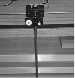
It’s used experimental setup for performance analysis. The techniques benchmarked on experimental setup. The system is shown in Fig. 1. The experimental setup consists of a pendulum bonded to cart that fixed on the horizontal position of the flexible-joint manipulator. All components, system specifications and details are presented by Quanser [27].
Fig. 1a) Electromechanical model of Flexible-Joint manipulator, b) its schematic illustration
a)
b)
3. Modelling of the system
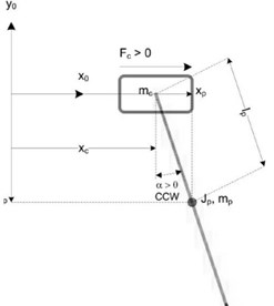
To obtain mathematical model used Lagrange’s method. Cart moves in the horizontal plane and the pendulum in a vertical plane. Then, the equations of motion of the flexible system are [27]:
where; is the mass of the pendulum, equivalent inertia of the cart system, pendulum moment of inertia, pendulum length from pivot to centre of gravity, equivalent viscous damping coefficient, viscous damping coefficient, as seen at the pendulum axis, gravitational constant of earth, linear force applied to the cart is generated by the servo motor, sliding member (cart) position and pendulum swing angle.
4. Shaped reference command
Input shaping is a command generation technique that reduces vibration by suitably shaping the reference signal such that the vibratory modes of the system are cancelled. Shaped command profiles are generated by two ways. First is convolving a sequence of impulses, other is solving special functions for the desired command signal. New command profiles are formed by using system natural frequency and damping ratio.
This process is shown in Fig. 2. Note that the rise time of the command is lengthened by the duration of the shaper. In general, the rise time of the input-shaped system will closely track the command rise time, so minimizing the shaper duration is important for achieving high-speed motion [1].
The percentage vibration can be determined by using the expression for residual vibration of a second order harmonic oscillator of frequency rad/s and damping ratio , which is given in Bolz and Tuve [29]. The vibration from a series of impulses is divided by the vibration from a single impulse with unity magnitude to get the vibration percentage as follows:
where and are the amplitudes and time locations of the impulses, is the number of impulses in the input shaper, and is the time of the last impulse.
Fig. 2Input shaping process (Singh [28])
![Input shaping process (Singh [28])](https://static-01.extrica.com/articles/16725/16725-img3.jpg)
4.1. Zero vibration (ZV) input shaper
Basic input shaper in literature is Zero Vibration (ZV) input shaper. Constraints for shaper are zero vibration and minimal time at the modelling frequency. If Eq. (3) is set equal to zero and it is used to design an input shaper, then the resulting shaper is called a Zero Vibration shaper. Durations and amplitudes of the ZV shapers are [1, 13]:
where and .
In operation, ZV shapers can be very sensitive according to modelling errors. To examine this possibility, the amplitude of residual vibration can be plotted as a function of the modelling errors. Sensitivity curve for the ZV shaper is seen in Fig. 3. Notice that the vibration amplitude increases rapidly as the actual frequency deviates from the modelling frequency [1, 16].
4.2. Derivative methods (ZVD, ZVDD, ZVDDD input shapers)
The earliest form of robust input shaping was achieved by setting the derivative, with respect to the frequency, of the residual vibration Eq. (3) equal to zero. The resulting shaper is called a Zero Vibration and Derivative (ZVD) shaper. The times and magnitudes for this shaper are [1, 13]:
It is clearly seen in Fig. 3 that the ZVD shaper is much more insensitive to modelling errors than the ZV shaper. However, the ZVD shaper is of time duration equal to one period of the vibration frequency, as opposed to the one-half period length of the ZV shaper. This trade-off is typical of the input shaper design process, increasing insensitivity usually requires increasing the length of travelling time of the input shaper [16].
An input shaper with even more insensitivity than the ZVD can be obtained by setting the second derivative of Eq. (3) with respect to equal to zero. This shaper is called the ZVDD shaper. The algorithm can be extended indefinitely with repeated differentiation of the percentage vibration equation. For each differentiation, an additional impulse is added to the shaper and the shaper is lengthened by one-half period of the frequency [16].
The times and magnitudes for ZVDD and ZVDDD shapers are [1]:
where .
where .
ZVDD and ZVDDD sensitivity curves are shown in Fig. 3.
4.3. Extra intensive (EI) input shapers
Unlike the ZV, ZVD and ZVDD shapers, the Extra Insensitive (EI) shaper does not attempt to force the vibration to zero at the modelling frequency. Rather, the vibration is limited to some low, but acceptable level of residual vibration. The sensitivity curve for an EI shaper designed to limit vibration below 5 % is shown in Fig. 3.
The magnitudes and times for EI input shaper are [14]:
where is the tolerable level of vibration. For a system is of viscous damping, the EI shaper is described by Vaughan et al. [1] and Singhose et al. [14]:
where:
The length of the EI shaper is the same as that of the ZVD shaper, one damped cycle of vibration, but it is considerably more robust. Thus, the application of EI shapers is for systems where some small vibration is allowable, and the systems parameters are expected to change considerably.
4.4. Two hump extra intensive input shapers
Shapers that extend extra insensitive shaper idea have a progressively larger number of humps and are called multi-hump EI shapers. For undamped systems, the two-hump EI is described by Singhose et al. [14].
Unlike the ZV, ZVD and ZVDD shapers, the Extra Insensitive (EI) shaper does not attempt to force the vibration:
where:
The sensitivity curves for two-hump EI are shown in Fig. 3. Note that the two-hump EI shaper suppresses vibration over the entire range shown. As with the derivative-method shapers, the price for increased robustness is a corresponding increase in shaper duration. Note, however, that the penalty is not uniform across all shapers. The two-hump EI has the same duration as the ZVDD shapers. However, the two-hump EI shapers have much more robustness, as can be seen in Fig. 3.
4.5. Modified input shaping (MIS) techniques
Another important method worth mentioning is called Modified Input Shaping (MIS) technique that requires the use of a certain minimum number of impulses. This technique forms modified input-shaping zero vibration (MISZV) shapers that have zero vibration at the modelled frequency, but have a larger number of impulses and longer shaper duration than the ZV shaper. An -impulse MISZV shaper is described by Shan et al. [2]:
where:
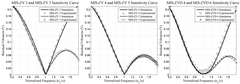
The sensitivity plots for two to five-impulse MISZV shapers are shown in Fig. 4. One can see that the additional impulses only provide a minimal increase in shaper insensitivity.
By definition Zero-derivative MIS (MISZVD) shapers are formed by convolving two MISZV shapers designed for the same frequency. The resulting MISZVD shaper is indicated by the number of impulses of each of the MISZV shapers used to create it. An × – impulse MISZVD is formed by convolving an MISZV shaper containing impulses with an MISZV shaper with impulses [1, 2]. Though convolving of MISZV shapers of higher number of impulses results in more robust MISZVD shapers, at the cost of increased shaper duration. It should be noted that a 2×2-impulse MISZVD shaper is the traditional ZVD shaper. The sensitivity plots for 2×2 and 2×3-impulse MISZVD shapers are shown in Fig. 4.
4.6. Cycloid plus ramped versine plus ramp (CPRVPR) reference function
Cycloid plus ramped versine plus ramp (CPRVPR) function is made up of three functions. The total distance to be covered from the beginning to end of a move within a specified time is the sum of the distances to be travelled by each of the three functions within the same travel time. By adjusting excursion distance of each function, vibration can be eliminated provided that the specified move time and the total distance are unchanged. Each component of the reference input creates oscillations such that these oscillations cancel each other out resulting in reduction or elimination of residual vibration.
A motion profile of a CPRVPR function is expressed as [24]:
where is the maximum excursion distance to be travelled by ramp motion profile, is the maximum excursion distance to be travelled by cycloid motion profile, is the maximum excursion distance to be travelled by ramped versine motion profile, is time into motion, is the travelling time, and . Furthermore, total distance can be written as , then arranging the equation above becomes:
The corresponding velocity profile is:
The excursion distance values (, and ) for zero residual vibration with zero initial conditions [24]:
where is the natural period and is the natural frequency. Variations of , and is possible with traveling time to result in an oscillation free displacement of the system.
Cycloid plus ramped versine plus ramp function sensitivity curves are shown in Fig. 5. Theoretically, there is no travelling time restriction on the system and this is the main advantages of this reference command [24].
4.7. Hybrid input shaper
In this method, a pre-shaped command is produced by combining the different template functions to allow the resulting trajectory and the travelling time being adjustable. Then this pre-shaped input is convolved with sequence of impulses. This sequence of impulses is obtained using the input shaping described in Section 4.1. to increase the robustness of the signal. The method suggested by Yavuz et al. [25] is named as hybrid input shaping. For a specified travelling time and displacement, hybrid-shaping technique is implemented as follows;
• Travelling time for the template function is calculated from in order to satisfy the total travelling time . Here, total travelling time, , should be greater than delay time, .
• The distances , and for the template functions are calculated from Eq. (16),
• The resulting trajectory is convolved with the two impulse sequence defined by Eq. (4).
The sensitivity curves for hybrid input shaping method are shown in Fig. 5. It can be seen from Fig. 5 that the vibration is considerably eliminated by convolving the pre-shaped input of cycloid plus ramped versine ramp function with the sequence of all modes generated by two impulse sequences.
4.8. Modified cycloid plus ramped versine plus ramp (M-CPRVPR) reference function
The modified CPRVPR reference function utilises the cycloid plus ramped versine plus ramp reference function presented in Section 4.6. Eqs. (13)-(16) are used to obtain the command input required for the system. In contrast, it’s divided the travelling time into two sections and calculated the command input as two separate inputs and then joins them to form the new input with this method.
The calculations for the method are as follows where the input is divided into two sections and each one is calculated independently to form the first and the second part of the input signal. A motion profile of a modified CPRVPR function is described by Conker et al. [26]:
where:
As defined in Eq. (17), this method allows a virtual division of the motion of the system into two steps. Because the first step is completed with almost steady motion and with relatively reduced vibration levels, the second part of the motions starts with the advantage of very little or almost no residual vibrations. As a result of the second part of the motion yields better performance to the CPRVPR method [26].
5. Comparison of shaped reference commands
In the previous sections some selected positive and smoothly shaped reference command methods are presented. Further details on the presented methods are available by referring to the relevant references. The successful implementation of the presented input shaping methods requires accurate estimation or determination of the damping ratio and natural frequency of the system in concern. However, the mathematical models of any system, especially flexible systems, cannot be modelled properly. The variations of the system parameters or noisy environments would affect the shaped input signal. These changes would also affect the system response. For the shaping process to be effective in noisy industrial environments, the shaper must have robustness to external disturbances such as uncertainty regarding system parameters or external noise sources. The benefit of the robust techniques is that they have a wider frequency range for which the results are insensitive to estimation errors of natural frequency. Therefore, the robustness of shaped signal to modelling uncertainty is an important performance comparison tool for command shaping methods. In this section, the presented methods are compared for length of travelling time and also their robustness for system parameter estimation errors.
In Table 1 and Fig. 3 and 4, the performance evaluation criteria for positive input shapers are provided. From the details provided in Table 1, it can be concluded that;
• The ZV shapers are quite sensitive according to modelling errors; a small error when calculating system frequency causes considerable residual vibrations.
• The ZVD shapers are of significantly more robustness to modelling errors. It is evident by noting that the width of the ZVD curve is much larger than the width of the ZV curve.
• The ZVD shaper is of additional insensitivity but this incurs a time penalty; the ZVD shaper travelling time is longer than the ZV shaper’s by one half period of the vibration. In most cases, this time lag is not considered to get large increase in robustness.
• The performance of MISZV stands between ZV and ZVD. The travelling time and robustness properties of the MISZV method stand in between ZV and ZVD methods. Each additional impulse to the reference command improves the robustness performance while extending the travelling time.
• The EI shaper is essentially the same length as the ZVD shaper, but it is considerably more robust. The two-hump EI has the same duration as the ZVDD. However, the two hump EI shapers have much more robustness.
• Performances of the techniques are compared for Efficiency of insensitivity [1] for which it is shown that two hump extra insensitive (2HEI) seems to be the best of all.
Fig. 3ZV, ZVD, ZVDD, ZVDDD, EI, two hump EI input shapers experimental and simulation of sensitivity curve
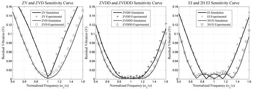
Fig. 4MIS-ZV2, MIS-ZV3, MIS-ZV4, MIS-ZV5, MIS-ZVD4, MIS-ZVD6 input shapers experimental and simulation of sensitivity curve
In Table 2 and Fig. 5, the performance evaluation criteria for smoothly shaped reference commands are provided. From the details provided in Table 2, it can be concluded that:
• The time delay for the input shapers increases with increasing insensitivity. This indicates that there is a conflict between shaper robustness and shaper time delay just as in the case of other input shaping methods.
• The CPRVPR reference function is quite sensitive to modelling errors; a small errors in the modelling frequency leads to considerable residual vibrations.
• Hybrid input shaper is much more insensitive to modelling errors than the CPRVPR reference function. However, the Hybrid input shaper has a time duration equal to one period of the vibration frequency, as opposed to the one-half period length of the CPRVPR reference function.
• Performances of the techniques are compared for Efficiency of insensitivity [1] for which it is shown that Modified CPRVPR reference function seems to be the best of all.
Fig. 5CPRVPR, Hybrid and M-CPRVPR Input shapers experimental and simulation of sensitivity curve
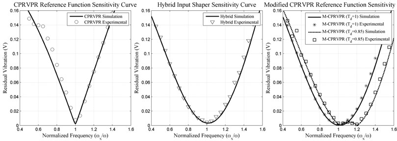
Table 1Performance criteria for comparison of positive input shaper
ZV | ZVD | ZVDD | ZVDDD | EI | 2HEI | MISZV | MISZVD | |||||
2 | 3 | 4 | 5 | 2×2 | 2×3 | |||||||
Duration (cycle) | 0.5 | 1 | 1.5 | 2 | 1 | 1.5 | 0.5 | 0.665 | 0.749 | 0,799 | 1 | 1.16 |
Robustness 5% | 0.063 | 0.2876 | 0.480 | 0.627 | 0.40 | 0,732 | 0.063 | 0.082 | 0.090 | 0.094 | 0.287 | 0.332 |
Efficiency of insensitivity [1] | 0.126 | 0.287 | 0.32 | 0.3135 | 0.4 | 0.488 | 0.126 | 0.124 | 0.121 | 0.1176 | 0.287 | 0.286 |
Table 2Performance criteria for comparison of smoothly shaped reference commands
CPRVPR | Modified CPRVPR | Hybrid input shaping | ||
Duration (cycle) | 0.5 | 0.85 | 1 | 1 |
Robustness 5 % | 0.0585 | 0.3439 | 0.2755 | 0.2754 |
Efficiency of insensitivity [1] | 0.117 | 0.4045 | 0.2755 | 0.2754 |
6. Conclusions
This paper presents a review of command pre-shaping methods and investigates the compromise between rapidity of motion and shaper robustness. In this study, in total of 15 different input shaping methods are reviewed. The reviewed methods cover almost all types of positive shapers and smoothly shaped reference commands reported in literature. Therefore, the presented review study provides almost a complete picture of the topic for the researchers working in the area. The study is structured in a way that it provides all the necessary theoretical background and the implementation related details for each of the method presented. In addition, the presented methods are also used for comparative study of robustness and travelling time features. Furthermore, a comparison table is also provided in which each group of methods are listed for their efficiency of insensitivity according to the simulation studies performed.
From the details of the presented study it can be concluded from experimental and simulation results that:
• The shaper must have robustness to uncertainty regarding system parameters for the shaping process to be effective on real systems. The benefit of the robust techniques is that they have a wider frequency range for which the results are insensitive to estimation errors of natural frequency.
• The robust shapers typically have longer travelling times that leads to slower the system response. This creates a compromise between shaper robustness and rise/travelling time.
• The increasing travelling time appears to cause increasing robustness that is mostly method dependent. Hence, the compromise on increasing travelling time gains increasing robustness that varies from a method to another. In other words, the efficiency of insensitivity varies from one method to another.
• The comparative study of the methods for efficiency of insensitivity indicate that the best method for positive input shapers is two hump extra insensitive (2HEI) with value of 0.488, and for smoothly shaped reference commands is Modified CPRVPR ( 0.85) with value of 0.4045.
In conclusion, the presented review paper provides the details on the theoretical background, implementation details, related simulation and experimental results and comparative study of most of the input shaping methods in literature. Due to its content and the details provided, it becomes a rough guide for selection of an input method for specific robustness, travelling time and mathematical calculation related computing complexity requirements.
References
-
Vaughan J., Yano A., Singhose W. Comparison of robust input shapers. Journal of Sound and Vibration, Vol. 315, 2008, p. 797-815.
-
Shan J., Liu H., Sun D. Modified input shaping for a rotating single-link flexible manipulator. Journal of Sound and Vibration, Vol. 285, 2005, p. 187-207.
-
Singhose W., Pao L. A comparison of input shaping and time optimal flexible body control. Control Engineering Practice, Vol. 5, Issue 4, 1997, p. 459-467.
-
Singhose W., Porter L., Kenison M., Kriikku E. Effects of hoisting on the input shaping control of gantry cranes. Control Engineering Practice, Vol. 8, Issue 10, 2000, p. 1159-1165.
-
Chan T., Godbole K., Hou E. Optimal input shaper design for high-speed robotic workcells. Journal of Vibration and Control, Vol. 9, Issue 12, 2003, p. 1359-1376.
-
Dharne A. G., Jayasuriya S. Robust adaptive control of residual vibration in point-to-point motion of flexible bodies. Journal of Vibration and Control, Vol. 13, Issue 7, 2007, p. 951-968.
-
Gürleyük S. S., Cinal S. Robust three-impulse sequence input shaper design. Journal of Vibration and Control, Vol. 13, 2007, p. 1807-1818.
-
Blackburn D., Singhose W., Kitchen J., Patrangenaru V., Lawrence J., Kamoi T., Taura A. Command shaping for nonlinear crane dynamics. Journal of Vibration and Control, Vol. 16, Issue 4, 2010, p. 477-501.
-
Kim D., Singhose W. Performance studies of human operators driving double-pendulum bridge cranes. Control Engineering Practice, Vol. 18, Issue 6, 2010, p. 567-576.
-
Smith O. J. M. Posicast control of damped oscillatory systems. Proceedings of the Institute of Radio Engineers, Vol. 45, 1957, p. 1249-1255.
-
Singer N. C., Seering W. P. Using acausal shaping techniques to reduce robot vibration. IEEE International Conference on Robotics and Automation, New York, USA, 1988, p. 1434-1439.
-
Singer N. C. Residual Vibration Reduction in Computer Controlled Machines. Ph.D. Thesis, MIT Artificial Intelligence Laboratory, Massachusetts, 1989.
-
Singer N. C., Seering W. P. Preshaping command inputs to reduce systems vibration. Journal of Dynamic Systems Measurement and Control, Vol. 112, 1990, p. 76-82.
-
Singhose W., Seering W., Singer N. C. Residual vibration reduction using vector diagrams to generate shaped inputs. ASME Journal of Mechanical Design, Vol. 116, 1994, p. 654-659.
-
Singhose W., Seering W. P., Singer N. C. Input shaping for vibration reduction with specified insensitivity to modeling errors. Proceedings of Japan – USA Symposium on Flexible Automation, Boston, USA, 1996.
-
Singhose W., Porter L., Singer N. C. Vibration reduction using multi-hump extra insensitive input shapers. American Control Conference, USA, Vol. 5, 1995, p. 3830-3834.
-
Singhose W. Command shaping for flexible systems: a review of the first 50 years. International Journal of Precision Engineering and Manufacturing, Vol. 10, Issue 4, 2009, p. 153-168.
-
Aspinwall D. M. Acceleration profiles for minimizing residual response. ASME Journal of Dynamic Systems, Measurement and Control, Vol. 102, Issue 1, 1980, p. 3-6.
-
Meckl P. H., Seering W. Experimental evaluation of shaped inputs to reduce vibration for a Cartesian robot. ASME Journal of Dynamic Systems, Measurement and Control, Vol. 112, 1990, p. 159-165.
-
Piazzi A., Visioli A. Minimum-time system-inversion- based motion planning for residual vibration reduction. IEEE/ASME Transactions on Mechatronics, Vol. 5, Issue 1, 2000, p. 12-22.
-
Sahinkaya M. N. Input shaping for vibration-free positioning of flexible systems. Proceedings of the Institution of Mechanical Engineers, Part I, 2001, p. 467-481.
-
Sahinkaya M. N. Exponential input shaping for vibration free positioning of lightly damped multi-mode systems. 7th International Conference on Motion and Vibration Control, 2004, p. 8-11.
-
Alıcı G., Kapucu S., Baysec S. On preshaped reference inputs to reduce swing of suspended objects transported with robot manipulators. Mechatronics, Vol. 10, 2000, p. 609-626.
-
Kapucu S., Alıcı G., Baysec S. Residual swing/vibration reduction using a hybrid input shaping method. Mechanism and Machine Theory, Vol. 36, 2001, p. 311-326.
-
Yavuz H., Mistikoglu S., Kapucu S. Hybrid input shaping to suppress residual vibration of flexible systems. Journal of Vibration and Control, Vol. 18, Issue 1, 2011, p. 132-140.
-
Conker C., Kılıc A., Mıstıkoğlu S., Kapucu S., Yavuz H. An enhanced control technique for elimination of residual vibrations in flexible-joint manipulator. Strojniškivestnik – Journal of Mechanical Engineering, Vol. 60, Issue 9, 2014, p. 592-599.
-
Quanser, Linear Pendulum Gantry Experiment for MATLAB/Simulink Users.
-
Singh T. Optimal Reference Shaping for Dynamical Systems: Theory and Applications. CRC Press, Boca Raton, 2010, 21-24.
-
Bolz R. E., Tuve G. L. CRC Handbook of Tables for Applied Engineering Science. CRC Press, Inc., Boca Raton, FL, 1973.
Cited by
About this article

