Abstract
New trajectory planning method for mobile piezorobots is presented in this paper. Non-rotated mobile piezorobots must move by the given trajectory at the maximum speed and precisely replicate the given path. Two segments excitation schemes, which are used for formation of motion trajectory, were analyzed. Trajectory planning method was verified with numerical experiments and with the experimental system in the laboratory.
1. Introduction
Many industrial applications need to manipulate different types of objects with high accuracy, therefore it is important to use precise positioning systems with nanometric resolution. Most high precision positioning devices are driven by piezoelectric actuators. They have the following advantages: high resolution, short response time, good controllability and etc. [1-3].
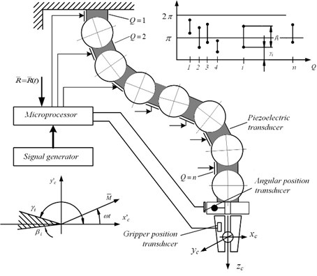
Description of a theoretical background of systematic computer algebra methods for analyzing the real-time dynamics of robots with a large numbers of joints was presented [4]. The first schematics of trunk robots (Fig. 1(a)) were given based on friction control between links by high frequency oscillations or by applying electrorheological fluids with controllable viscosity.
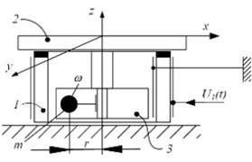
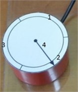
Fig. 1a) The schematic of robot with a large number of joints and b) a case of positioning device on the plane: 1 – piezoelectric cylinder with radial poling, 2 – table, 3 – electric motor with unbalanced rotor, generating centrifugal force Pc (outward force, apparent in a rotating reference frame, Pc=mrω2); c) piezorobot top view, where 1, 2, 3, electrode’s segments, 4 – orientation arrow
a)
b)
c)
Fig. 1(a) presents schematic of a new class of multi-degree-of-freedom trunk robots, based on new concept to generate motion of the grip. Classical rule of robotics says that the number of degree-of-freedom of robot should be equal to the number of applied actuators however we propose a new principle of the robot actuation. A new idea is to actuate trunk of the robot. The following advantages will be achieved: considerably increase number of degree-of-freedom, enabling the grip to reach hardly accessible zones; highly reduced number of actuators (e.g. electric motors) – up to 1 (and it is not related to total number of degree-of-freedom of trunk robot); very simplified mechanical design and low weight (this is important for satellite applications).
The trajectories of grip are realized by applying special software, controlling in real time the number of degree-of-freedom of every kinematic pair in relation to the phase of external force with alternating direction (in case when the force is generated by rotating unbalance).
The following trajectory planning algorithms for these 3DOF piezorobots (piezoelectric ring, piezoelectric cylinder and piezoelectric hemispheric) under two contacts excitation schemes were created [6]: switching contacts, control points and tangents methods. All developed mobile piezorobot electrodes are divided into three equal segments.
Linear movement is formed using only one excited electrode in switching contacts algorithm. If one electrode segment of robot is active at a time, then motion trajectory is a broken line. The trajectory formed with this algorithm is not precise, but the control of piezorobot is the simplest.
Both control points and tangents algorithm are using same segments excitation schemes. One scheme is used for linear movement formation, when one segment is excited. The second scheme is used for all three electrodes that are excited at the same time, to achieve the traveling wave. Then the robot will rotate around the z-axis. The principle of the control points method is to divide a given trajectory into equal length segments and make rotation movement at points joining these segments. These points are called control points. The method is suitable for the motion in continuous curves. This method was created to form high-precision trajectories. The method of tangents is designated to shape the trajectory that is optimal in respect of speed but maintain the accuracy of motion. Comparison of all three algorithms is presented in Table 1 [7].
Table 1Comparison of algorithms of trajectory planning
Switching contacts | Control points | Tangents | |
Number of segments excitation schemes used for trajectory formation | 1 | 2 | 2 |
Number of active segments used for linear motion | 1 | 1 | 1 |
Number of active segments used for rotation around its central axis (-axis) | 0 (not rotating) | All segments | All segments |
Is it used for forming precision trajectories? | No | Yes | No |
Is it used for forming high speed trajectories? | No | No | Yes |
The following requirement was formulated for a new trajectory planning algorithm i.e. non-rotated mobile piezorobots must move precisely by given trajectory at maximum speed. The most accurate method for movement along the given trajectory is the contact point algorithm, but velocity of the piezorobot is slow because traveling wave is used for the rotation. Therefore, developed till now trajectory planning algorithms cannot be used. New algorithm allows to excite two or more electrodes at the same time for obtaining linear motion of the piezorobot.
2. Fine trajectory planning method
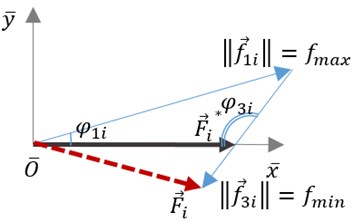
Let’s analyze piezorobot that have three electrodes (Fig. 2) and assume that two electrode segments can be excited at the same time with different forces , where is number of trajectory point, is number of segment 1, 2,…, , where is quantity of segments. The movement forming force of the piezorobot is proportional to the voltage on each segment and is controlled by changing the amplitude of a sinusoidal signal. Eq. (1) is used to calculate the total force:
Fig. 2Trajectory planning scheme
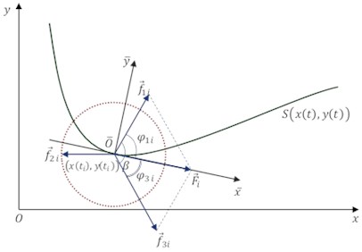
Mobile piezorobot is moving by a given parametric trajectory in two-dimensional space, where is parameter. Results are forces of separate electrode segment and their total force at the trajectory point . The problem was solved in two different situations: when and .
Orientation of the total force is the same as tangent line orientation at trajectory point .
Since the aim is to maximize traveling velocity of the piezorobot, so electrode segment, that is closed to the total force vector must be selected for the excitation and its numeric value are equal to maximum:
where
Forces of the individual electrode segments are equal to:
where is proportionality coefficient and can be calculated by formula:
where is angle between segments.
If the angle between the total force and the segment force is more than angle between segment forces, then segment force value is equal to zero. So this electrode segment is turned off. The last segment is calculated using Eq. (4).
When all values of the segments are known, then the total force is calculated as follows:
where:
When the numeric value of the force is between minimum and maximum values or the segment is turned off we have more complicated case. There also can be a situation, when value of one of two forces is less than minimum, then it should be equated to this minimum value. In this case, an error of the direction of the total force occurs and piezorobot deviates from the given trajectory (Fig. 3(a)).
In order to maintain the most accurate replication of the path, an inactive segment is turned on (Fig. 3(b)). The value of the force of this segment is equal to minimum value. So one force, which is the nearest to the total force orientation, is equal to maximum value, and the other force, which is cardinally in the opposite orientation, is equal to the minimum value.
Fig. 3Scheme of segments forces and the total force
a) The error of the direction of the total force
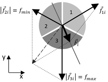
b) Situation, when inactive segment no. 2 is turned on
Numeric values of the third force and the total force are unknown. These values were calculated after solving the system of equations:
where is angle between tangent line and -axis and:
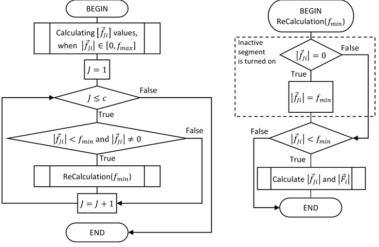
Both analyzed cases i.e. when and can be combined in general algorithm that is shown in Fig. 4.
Fig. 4Fine trajectory planning algorithm
3. Analysis of trajectory planning algorithm
A mathematical model of proposed trajectory planning algorithm was evaluated with a given trajectory and in both situations when [0, 5] N and [2, 5] N. The given trajectory is equal to when –3.153.15. The orientation (angle between the first electrode segment and global -axis) of the piezorobot was changed {20°, 40°, 60°}
The results of numerical experiment showed that when [0, 5] then one segment is always turned off, but the other values of segments change smoother in the requirement range (Fig. 5(a)). It can be noticed that the average of the total force is independent on piezorobot orientation. After calculations of average total force and standard deviation it can be concluded that the total force value is equal to 4.542±0.196 N. The force value changed in the very small range, so the speed will be close to the maximum and the movement will be smoother.
Furthermore, when the force must be in the specific range, one value of the segment is always equal to maximum, sometimes inactive segment is turned on and then the third force value is increasing and is more than minimum value, but significantly reduces the total force at the same time (Fig. 5(b)). The total force value is changing in the range [2.615; 4.961] N. In this case the total force value will be equal to 3.831±0.879 N. The force value changed in the wider range, so there will be loss of speed (force) in some trajectory points.
The loss of the force in some trajectory points was calculated in these experiments. This calculation was repeated with different trajectories and with different minimum and maximum ranges. This showed that the loss of the total force is the same for the identical proportion of the range (Fig. 6). It gives an opportunity to assess the average maximum speed and select the most appropriate range for forces.
Fig. 5Numerical experiments results
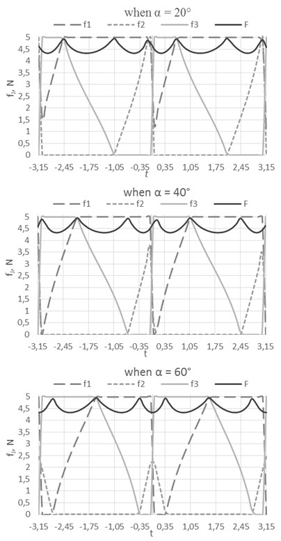
a)[0, 5] N
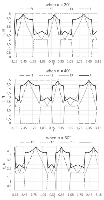
b)[2, 5] N
Fig. 6The loss of the total force
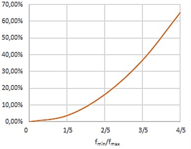
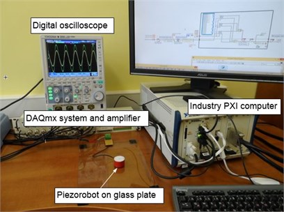
Fig. 7The three degree of freedom computer based control system
4. Experimental study
An experimental system was developed in order to validate proposed trajectory planning method. It consists of two main parts: a piezoelectric cylinder as piezorobot prototype and the control system. Piezorobot is located on a glass plate. The interface to hardware output was set according to the technical requirements of National Instruments NI-DAQmx hardware [8, 9]. The experimental system is shown in the Fig. 7.
Piezorobot control system consists of LabVIEW-based control software that was designed to operate on Industry PXI (PCI eXtensions for Instrumentation NI PXIe-1062Q) computer system (Fig. 8).
Fig. 8The structure of the piezorobot control system
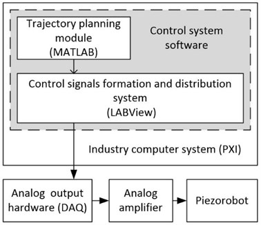
Fig. 9Piezorobot control system block diagram
The program consists of trajectories planning module based on MATLAB and was used to calculate the trajectories of the piezorobot [10]. Control signals formation and distribution system forms analog signal sequence for piezorobot control. Analog output hardware DAQ (Data Acquisition NI PXIe-6368) is a physical equipment that distributes the analog signals to the physical outputs. The analog amplifier is necessary for signal amplification because piezorobot moves with the high voltage (up to 160Vp-p) sinusoidal signal.
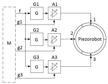
The control system is based on the trajectory planning MATLAB software that was integrated into the LabVIEW program (Fig. 9). MATLAB software module (M) forms a sinusoidal frequency control signal (f) for controlling three sinusoidal signal generators G1, G2 and G3. Generators generate sinusoidal signal 52.5 kHz for the piezorobot control. Amplitude control signals (g1, g2, g3) change the amplitude of each signal at the right time and manage the amplifiers A1, A2 and A3. Enhanced signal is supplied to each of piezorobot segments 1, 2, and 3 individually managing each of the amplitude according to a calculating algorithm by mathematical module M. The mathematical module calculates variables values accordingly giving control algorithm of the piezorobot.
Hardware control software (Fig. 10) was created on LABView, using MATLAB script as a mathematical module. The trajectory formatting speed was set manually using clock (in milliseconds) with external multiplication. 3 channel sine wave generator was programed by LABView and controlled by MATLAB script.
Extensive experiments were conducted in order to confirm validity of the piezorobot control methods and algorithms. Control experiments were carried out using experimental system and it was found out that piezorobot moves by a given trajectory in two ways: when it has ellipse type trajectory (Fig. 11(a)) and when trajectory is a curve (Fig. 11(b)). Trajectory points were obtained when making pictures of the moving piezorobot by photo camera at discrete time points.
The force of the piezorobot segments is proportional to the control signal amplitudes which have been monitored by a digital oscilloscope. It was found that moving trajectory of the piezorobot is very similar to the given one. Precision measurements have not been performed since the system was designed only to validate the proposed trajectory planning method. Precise measurement of the trajectory is expected to make in the future when experimental system will be supplemented with video camera and image processing tools as feedback elements.
Fig. 10Control software LABView block diagram
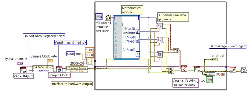
Fig. 11The real trajectories of piezorobot, where ● is start point, ○ is points at discrete time, and –––– is programmed coordinates
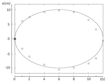
a) Ellipse trajectory when
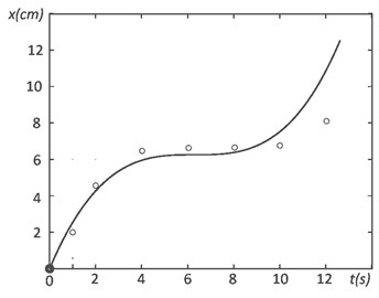
b) Curve trajectory when
5. Conclusions
A new trajectory planning method was proposed and evaluated. Motion of the piezorobot is formed by using new segments excitation scheme when two or more segments are excited to obtain linear motion without rotation. Trajectory planning method was validated using special experimental system. Piezorobot movement precisely replicate the given trajectory. The experiment was carried out with only one robot section. Whereas, Eqs. (4) and (5) were received full kinematics and dynamics equations of movement, so routes of several sections of 6 DOF robot can be calculated using the fine trajectory planning algorithm.
References
-
Richard M., Clavel R. Concept of modular flexure-based mechanisms for ultra-high precision robot design. Mechanical Sciences, Special Issue on Future Directions in Compliant Mechanisms, Vol. 2, 2011, p. 99-107.
-
Rochat F., Schoeneich P., Marti O., Bleuler H., Mondada F., et al. Cy-mag3De: magnetic climbing inspection robot. Proceedings of the 14th International Conference on Climbing and Walking Robots and the Support Technologies for Mobile Machines, 2011, p. 407-414.
-
Du Zhijiang, Shi Ruochong, Dong Wei A piezo-actuated high-precision flexible parallel pointing mechanism: conceptual design, development, and experiments. IEEE Transactions on Robotics, Vol. 30, Issue 1, 2014, p. 131-137.
-
Bansevičius R., Čepulkauskas A., Kulvietienė R., Kulvietis G. Computer algebra for real-time dynamics of robots with large numbers of joints. Computational Science, Lecture Notes in Computer Science, Vol. 3039, 2004, p. 278-285.
-
Bansevičius R., Čepulkauskas A., Kulvietienė R., Kulvietis G. Symbolic Calculation of the generalized inertia matrix of robots with a large number of joints. Computational Science, Lecture Notes in Computer Science, Vol. 3516, 2005, p. 643-650.
-
Bansevicius R., Drukteiniene A., Kulvietis G., Tumasonienė I. Design of mobile microrobot based on standing and travelling waves. International Journal of Advanced Robotic Systems: Mechatronics, Vol. 10, Issue 219, 2013, p. 1-7.
-
Bansevicius R., Drukteiniene A., Kulvietis G. Movement trajectory planning algorithm of rotating mobile piezorobot. Solid State Phenomena: Mechatronic Systems and Materials, Mechatronic Systems and Robotics, Vol. 164, 2010, p. 371-376.
-
Shujiao J., Yanmin L., Wanli Z. The design of data acquisition system based on virtual instrument. ICCSNT, 2nd International Conference, 2012.
-
Sumathi S., Surekha P. LabVIEW Based Advanced Instrumentation Systems. Springer, Berlin, Heidelberg, New York, 2007.
-
Ding Y., Sun B., Huang Y., Lin W., Qian F. Hybrid MATLAB and LabVIEW to implement an intelligent foundation fieldbus control system. Intelligent Control and Automation (WCICA), 8th World Congress, 2010, p. 4539-4543.
About this article

This research is funded by Research Council of Lithuania, Project No. MIP-084/2015.
Ramutis Bansevicius conceived the concept of mobile robots and multi-degree-of-freedom trunk robots. He also developed design of the investigated piezoelectric robot. Asta Drukteiniene developed fine trajectory planning method for piezorobot and conducted numerical experiments for verification of the created algorithm. Genadijus Kulvietis analysed and summarized trajectory planning algorithms of piezorobots. Eugenijus Macerauskas created experiment control system of piezorobot, designed LABView based piezorobot control software, and performs an experiment of the piezorobot control and movement by the calculated trajectory. Jurate Janutenaite was responsible for modelling and finite element analysis prior to experiments. Analysis allowed to determine suitable geometrical parameters, oscillations and contact points’ trajectories. Dalius Mazeika conducted numerical investigation of the piezoelectric robot and drafted the manuscript. All authors read and approved the final manuscript.
