Abstract
Increase of terrorist attack in the present time detects necessity of retrofitting of existent structures or design of new structures which can resist blast loads. In this research, a shear concrete wall subjected to explosive load will be analytically investigated. CFRP sheets will be applied for retrofitting the wall, and its performance in strengthening of the wall will be studied. Also a kind of shear composite wall is modeled and analyzed under the blast load. Results are compared, and advantages and disadvantages of these types of walls will be represented. Validation of analytical simulation is done by modeling of two experimental tests and good agreements have been obtained. Results show that pasting every other CFRP layers in vertical manner will increase performance of the wall as well as warping the entire wall by CFRP sheets. External reinforcement by CFRP will significantly improve energy absorption of the wall comparing use of steel sheets. Also, increase of number of layers causes consideration improve in energy damping and negligible effect on wall displacement.
1. Introduction
In 1996, John E. Crawford et al. [1] used the numerical analysis methods to compute retrofitted structures. It was shown that wrapping the columns by composite sheets enhance survivability of columns and prevent collapse in most cases. Renato Parretti et al. [2] conducted an experimental test to investigate the effect of carbon fiber orientation. Results showed that the ultimate capacity of ±45-degree FRP laminate strengthened rectangular columns is slightly lower than that of columns strengthened with fibers in the hoop direction. In 2005, M. N. S. Hadi [3] presented results of testing eccentrically loaded columns externally wrapped with two types of materials, GFRP and CFRP. He concluded that considerable gain in strength and ductility were obtained when columns are reinforced with CFRP (vertical straps and horizontally wrapped). In 2005, Tomasz Jankowiak et al. [4] presented a method and requirements of the material parameters identification for concrete damage plasticity constitutive analytical model. In 2010, Carlos Chastre et al. [5] conducted an extensive research on twenty-five experimental reinforced concrete columns confined with CFRP composites and subjected to axial monotonic compression. In this research a numerical model was also proposed to simulate the behavior of circular reinforced concrete columns strengthened with CFRP composites.
Explosive loads are much larger than normal loads of buildings. So far, numerous issues and articles have been proposed in various methods to increase the structural strength against this kind of loads. In this case can be mentioned an experimental and finite element (FE) research in retrofitting concrete and masonry structures with fiber reinforced polymer (FRP) composites for blast protection [6]. Also, a series of explosive tests on retrofitted RC wall showed decrease in maximum displacement of GFRP and CFRP retrofitted RC wall compared with the RC wall without retrofitting [7-9]. In 2004, John J. Myers. et al. [10] showed masonry walls retrofitted by FRP systems have been shown great benefits to resist blast loads. In 2005, B. Lu et al. [11] conducted a real blast load test with RC slabs retrofitted by FRP and SRP materials and higher blast resistance capacity of the retrofitted slabs compare with the slab without external reinforcement was concluded. Also, in 2009, Gordon P. Warn et al. [12] conducted an experimental investigation which showed that steel plate shear walls (SPSWs) has limited capacity in out-of-plane blast loadings.
The main objective of this study is to investigate the structural performance of reinforced concrete shear walls retrofitted by CFRP materials in the condition of blast loading. Effectiveness of steel plates in retrofitting RC shear walls will be examined afterwards.
2. Finite element models, loading and analysis
In this research, a concrete wall is modeled by ABAQUS [13] software. The basic concrete wall is reinforced by steel horizontal and longitudinal bars. This model is named as “RC-wall”. The other type of models is completely similar to the RC-wall, but is reinforced with CFRP sheets. In this case, three models are considered which are different in the direction of pasting of CFRP sheets. The model has horizontal CFRP layers is named as “R-H-CFRP” and the model with vertical CFRP layers is named as “R-V-CFRP”. In these two models the distance between CFRP layers is set to 25 cm. Also, a model is considered which has a complete external warping; it’s named as “R-ALL-CFRP”. The number of layers which is used has been taken into account as another variable. In order to have a comprehensive compare, these models are compared with a kind of composite wall which is simulated in the following way. The first type of composite wall which is modeled consists of a 2 mm steel sheet is placed in the middle section of the RC-wall. The second type is the RC-wall which is reinforced by two 2 mm steel sheet are placed on the external faces of the wall. These two models are named as “Intern-comp” and “Extern-comp”, respectively.
Validation of finite element modeling has been done by simulating a circular column similar to the laboratory sample which has been done by Carlos Chastre et al. in Portugal [5]. This model is named as the “evaluation model”.
As described before, operation of the six models of the concrete wall which are subjected to blast load will be compared. The models are assigned in three groups. The “RC-wall” model is in the first group. The second group consists of three models; “R-V-CFRP”, “R-H-CFRP” and “R-ALL-CFRP”; which are the RC-wall with external reinforcement of CFRP sheet. The third group has two composite walls; “Intern-comp” and “Extern-comp”. Typical views of these three groups are shown in Fig. 1. The wall has 5 m height, 5 m width and 50 cm thickness. Longitudinal bars in both directions are Φ20 @ 150 cm.
Fig. 1View of models: a) “RC-wall”, b) “R-V-CFRP”, c) “Intern-comp”
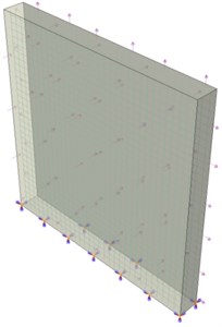
a)
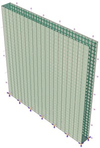
b)
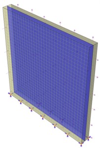
c)
Calculation for estimating the external blast loads has been represented which is according to UFC 3-340-02 [14]. Blast loads are pressure waves caused by the rapid release of energy during a chemical reaction. The wave propagation is spherical. in this research, it’s supposed that the models are subjected to explosive load is created of a 100 kg (220.46 lb) TNT bomb which is placed on the ground at 5 m of the wall. Explosive load is done according to “handbook for blast-resistant design of building” [15]. The scaled distance is found equaled to 2.71 m/kg(1/3). From this information the peak incident overpressure value of 130 psi and the reflected pressure of 650 psi were found using Fig. 6 of “The Handbook for Blast Resistant Design of Buildings” [15]. Additionally, the effective duration of the blast is found similarly about 0.005 s. Fig. 1 also shows how the load is applied to the walls. Fig. 1(a), presents the model of reinforced concrete wall (without extra retrofitting) and Fig. 1(b), (c) show the RC-wall with vertical CFRP layers and RC-wall with internal steel plate, respectively.
Material properties of CFRP sheets and steel rebar are represented in Table 1. Also, concrete compressive strength is assumed 50 MPa.
Explicit dynamic analysis has been used based on the nature of the explosive loads. This method of analysis is suitable for dynamic phenomena which happen too fast.
Table 1Mechanical properties of the materials
Ult. tensile strength | Ult. tensile strain (%) | Modulus of elasticity (GPa) | |
Steel bars | 400 MPa | 2.5 | 200 |
CFRP sheets | 6200 GPa | 1.5 | 240 |
3. Validation
3.1. First validation
In 2010, Carlos Chastre et al. tested 25 columns were subjected to monotonic axial compression. The columns were of plain or reinforced concrete, with different transversal sections and steel hoop spacing, and had been strengthened with an outer jacket of carbon fibers (CFRP) and tested under monotonic axial compression. This research was conducted in order to characterize the behavior of the plain concrete and reinforced concrete confined with CFRP.
Tomasz Jankowiak et al. [4] article has been used in order to define concrete damaged plasticity parameters which are used in the modeling. Also evaluation of correctness of modeling in ABAQUSE software has been done by Carlos Chastre et al. [5].
Geometric characteristics and material properties of the “evaluation model” are considered according to the laboratory test [5]. An elasto-plastic damage property is used to simulate the nonlinearity of concrete [16, 17] which is based on the classical continuum damage theory [18-20]. According to the recent analytical research, the 3-D linear brick solid element, C3D8, is considered to model concrete wall, shell element is used for simulation CFRP sheets and the linear truss element, T3D2, is used to model rebar in the ABAQUS [21-22]. Embedding technique is applied to interaction of rebars and concrete.
In this part, the result of “evaluation model” which is completely similar to the experimental work of Carlos Chastre et al. [5] is represented.
3.2. Experimental sample
The experimental research has been done by Carlos Chastre et al. [5] consisted of 25 samples of circular concrete columns. The samples were reinforced with CFRP sheets and were subjected to axial monotonic compression load. The graphs of axial force versus axial strain are obtained for the samples. Geometry and material characterization of the experimental column which is simulated as “evaluation model” are shown in Table 2.
Two layers of CFRP have been used for strengthening of the circular column. Static, Riks analysis is used for “evaluation model”. It’s an increasing nonlinear static analysis which is chosen because of load condition and materials non-linearity of the model. In order to find the best convergence with experimental result concrete damage plasticity and concrete smeared cracking are defined as plastic properties of concrete.
Table 2Geometry and material characterization of the experimental column
Height | Diameter | Longitudinal bars | Stirrup | Compressive strength of concrete | Yield strength of longitudinal steel | Yield strength of stirrup |
750 mm | 150 mm | Six Ф6 mm | Ф3 mm @ 15 cm | 38 MPa | 391 MPa | 323 MPa |
CFRP rupture strain | CFRP rupture stress | CFRP module of elasticity | Thickness of CFRP sheet | |||
1.44 % GPa | 3339 GPa | 226 GPa | ||||
3.3. Comparison of analytical and experimental results
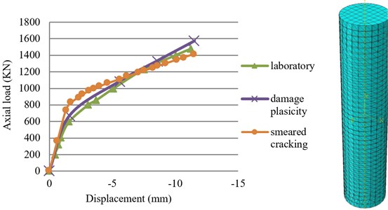
Axial force versus axial displacement curve of experimental sample and the “evaluation model” are represented in Fig. 2. As this figure shown, the result of the numerical model and the experimental sample shows acceptable adjustment with together, especially the model with concrete damage plasticity behavior shows more convergence than concrete smeared crack behavior. So, concrete damage plasticity will be used for the other models simulated in this research.
Fig. 2Comparison of force-displacement curves of experimental sample and “evaluation model”
3.4. Second validation
The second validation is done by simulating a slender reinforced concrete structural wall which was tested by Thomsen and Wallace [23] in 2004. The experimental specimen (RW1) is simulated in ABAQUS [13] by considering the damage plasticity behavior. The analytical results are compared with experimental results through the load- displacement curves. The shear wall RW1 height, width and thickness are 3600 mm, 1200 mm and 100 mm respectively. Fig. 3 shows detail of the sample RW1 [24], and the simulated model is shown in Fig. 4. For material properties and loading condition refer to reference No. 23. Results are obtained from Thomsen and Wallace [23] compared with analytical results through the load-displacement curve. Fig. 5(a) and Fig. 5(b) show load-displacement curve obtained from experimental test [23] and finite element analysis respectively. Comparison of these two figures confirms that the behavior of the simulated wall has good agreement with the experimental specimen.
4. Results
4.1. Force-displacement curves
Area under force-displacement curve represents the energy dissipation capability of the models. Fig. 6 shows how this ability can improve by strengthening of the RC-wall. The figure reveals external reinforcing of the RC-wall will be significantly helpful in its performance. The “RC-wall” and “Intern-comp” experienced more displacement relative than the other model. These two models endured about 140 mm drift during of loading time, while the other models met drift between 95 mm to 110 mm. All the models could experience the primal load of the blast. After it, some of the models consist of the composite models, the “RC-wall” and “R-H-CFRP” failed, and as the picture shows the curves of these models are falling. The models named as “R-ALL-CFRP” and “R-V-CFRP” could bear significant force before failure which present themselves as the best models in energy dissipation. The model “Extern-comp” dissipated energy less than the others because it met the lowest displacement and almost less force comparing with the other strengthened models, and “R-ALL-CFRP” has the best performance in this case.
Fig. 3The detail of the specimen RW1 tested by Thomsen and Wallace [24]
![The detail of the specimen RW1 tested by Thomsen and Wallace [24]](https://static-01.extrica.com/articles/16558/16558-img5.jpg)
Fig. 4The FE model of the wall tested by Thomsen and Wallace [23]
![The FE model of the wall tested by Thomsen and Wallace [23]](https://static-01.extrica.com/articles/16558/16558-img6.jpg)
Fig. 5Load-displacement curve: a) Experimental specimen RW1 [23], b) FE model
![Load-displacement curve: a) Experimental specimen RW1 [23], b) FE model](https://static-01.extrica.com/articles/16558/16558-img7.jpg)
a)
![Load-displacement curve: a) Experimental specimen RW1 [23], b) FE model](https://static-01.extrica.com/articles/16558/16558-img8.jpg)
b)
4.2. Effect of number of CFRP layers
Increase of numbers of CFRP layers leads to increase of displacement of all the models. Table 3 is numerically investigated the variation of the displacement in this case. Between these three models the most displacement occurred in the model with vertical CFRP layers. After it, the model reinforced with horizontal CFRP sheets met maximum displacement, and model warped completely with CFRP sheet had the least amount. Total view of the table shows that an increasing number of layers have negligible effect on displacement increasing. Fig. 7 shows how the increase of the number of CFRP layers leads to increase of endurance of the models which are not failed. Performance of the “R-H-CFRP” did not increase anymore and it is almost failed at the beginning of the loading. This figure obviously shows there is a significant difference between the operation of the “R-ALL-CFRP” and “R-V-CFRP”. The “R-ALL-CFRP” represents much better performance comparing the “R-V-CFRP”.
Fig. 6Force-displacement curve of the models
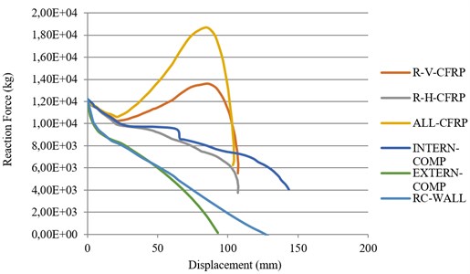
Fig. 7Effect of number of CFRP layers in force-displacement curves
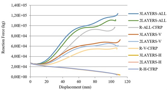
Table 3Effect of number of layers increasing on displacement
Number of layers | Complete CFRP | Vertical layer of CFRP | Horizontal layer of CFRP |
1 | 10.373 mm | 10.7052 mm | 10.7014 mm |
2 | 10.5429 mm | 10.8613 mm | 10.8549 mm |
3 | 10.8432 mm | 11.1131 mm | 11.1067 mm |
4.3. Failure investigation
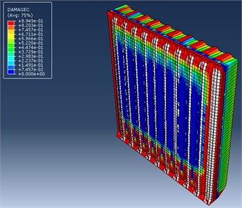
Fig. 8 shows the failure mode of the “R-V-CFRP”. All the models with CFRP layers resist to the blast load until tear of the layers. As Fig. 8 clearly shows the “R-V-CFRP” failed after that CFRP layers have torn.
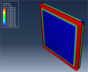
Failure is considered as a percentage of the area which is damaged relative to the area which is safe. So, the failure criteria is defined as a parameter between zero to one, zero is concerned to a completely safe model and one is assigned to a completely damaged model. As Fig. 9 shows 60 % of the “RC-WALL” failed and this is a relative heavy damage. Percentage of damage obviously decreased by using one layer of CFRP in the “R-ALL-CFRP”. In this model, damage area decreased to about 15 %. Fig. 9(c), (d) show “EXTERN-COMP” could decrease damage area about 35 % and the model “R-V-CFRP” will be helpful to damage decreasing about 25 %. Increasing in the number of CFRP layers will be creating much better condition.
Fig. 8Mode of failure of “R-V-CFRP”
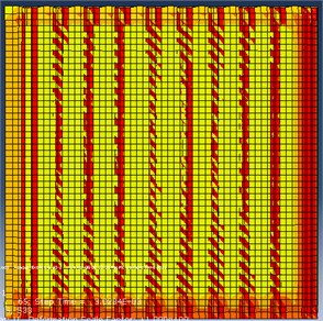
Fig. 9Failure percentage of the models
a) “RC-WALL”
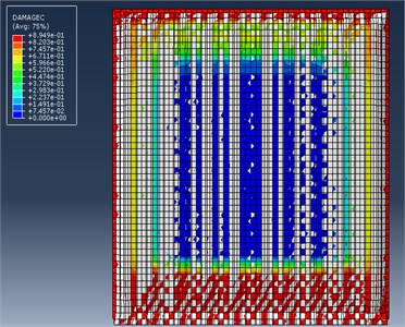
b) “R-ALL-CFRP”
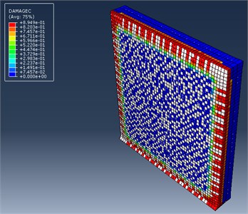
c) “EXPERN-CFRP”
d) “R-V-CFRP”
5. Conclusions
In this paper, the performance of a strengthened concrete wall under blast load is investigated. CFRP layers and steel sheets are used for strengthening of the wall. Results are listed below:
1) CFRP layers in a vertical manner significantly improved the ability of energy damping of the wall. Energy absorption in this case is about twice of the basic wall. Of course, the model which is entirely warped by CFRP layer represented better performance, but economically the model with every other CFRP layer is suggested, because of its need for half of CFRP material and showing 80 % performance of the “ALL-CFRP” model.
2) Number of layers is important in increasing of energy damping, but it has negligible effect on displacement. There is a main point which shows the entire covering of the wall with one layer of CFRP has much better performance than increasing of the number of layers in every other CFRP covering.
3) By external reinforcing of the RC-wall damage percentage will decrease from 60 % to 15 %. In this case, the best condition is obtained for the wall which entirely warped by CFRP sheets.
References
-
Crawford J. E., Malvar L. J., Dunn B. W., Gee D. J. Retrofit of reinforced concrete columns using composite wraps to resist blast effects. Proceedings of the 27th Department of Defense Explosive Safety Seminar, Las Vegas, NV, 1996.
-
Parretti Renato, Nanni Antonio Axial Testing of Concrete Columns Confined with Carbon FRP: Effect of Fiber Orientation. University of Missouri-Rolla and Co-Force America, 2002.
-
Hadi M. N. S. Eccentric loading of FRP wrapped concrete columns. 7th International Congress on Advances in Civil Engineering, Yildiz Technical University, 2006.
-
Jankowiak Tomasz, Ladygowski Tomasz Identification of parameters of concrete damage plasticity constitutive. Civil and Environmental Engineering, Vol. 12, 2005, p. 53-69.
-
Chastre Carlos, Silva Manual A. G. Monotonic axial behavior and modeling of RC circular columns confined with CFR. Engineering Structures, Vol. 32, 2010, p. 2268-2277.
-
Buchan P. A., Chen J. F. Blast resistance of FRP composites and polymer strengthened concrete and masonry structures – a state-of-the-art review. Elsevier, Composites: Part B, Vol. 38, 2007, p. 509-522.
-
Muszynski L. C., Purcell M. R. Use of composite reinforcement to strengthen concrete and air-entrained concrete masonry walls against air blast. Journal of Composites for Construction, Vol. 7, Issue 2, 2003, p. 98-108.
-
Muszynski L. C., Purcell M. R., Sierakowski R. Strengthening concrete structures by using externally applied composite reinforcing material. Proceedings of the Seventh International Symposium on Interaction of the Effects of Munitions with Structures, 1995.
-
Muszynski L. C., Purcell M. R. Composite reinforcement to strengthen existing concrete structures against air blast. Journal of Composites for Construction, Vol. 7, Issue 2, 2003, p. 93-97.
-
Myers John J., Belarbi Abdeldjelil, El-Domiaty Khaled A. Blast resistance of FRP retrofitted un-reinforced masonry (URM) walls with and without arching action. TMS Journal, 2004, p. 9-26.
-
Binggeng Lu, Pedro Franco Silva, Antonio Nanni, Jason Baird Retrofit for blast-resistant RC slabs with composite materials. 7th International Symposium on Fiber-Reinforced (FRP) Polymer Reinforcement for Concrete Structures, 2005.
-
Warn Gordon P., Bruneau Michel Blast resistance of steel plate shear walls designed for seismic loading. Journal of Structural Engineering, Vol. 135, 2009, p. 1222-1230.
-
ABAQUS: Theory Manual (Version 6.8). ABAQUS Inc., USA, 2008.
-
UFC 3-340-02. Structures to Resist the Effects of Accidental Explosions. Department of Defense, Washington, DC, 2008.
-
Dusenberry Donald O. Handbook for Blast Resistant Design of Buildings. John Wiley and Sons, 2010, p. 484.
-
Mark P. Investigations of reinforced concrete girders under biaxial shear using parametric finite element models. Computational Modeling of Concrete Structures (EURO-C 2006), Taylor and Francis/Balkema, Leiden, 2006, p. 739-746.
-
Bender M., Mark P. Shear bearing capacities of RC beams with circular sections. computational modeling and design. Proceedings of the 8th International Conference on Computational Structures Technology (CST 2006), Civil-Comp Press, Scotland, 2006, p. 289-290.
-
Yu T., Teng J. G., Wong Y. L., Dong S. L. Finite element modeling of confined concrete-II: plastic-damage model. Engineering Structures, Vol. 32, 2010, p. 680-691.
-
Mark Peter, Bender Michél Computational modeling of failure mechanisms in reinforced concrete structures. Architecture and Civil Engineering, Vol. 8, 2010, p. 1-12.
-
Lee H. K., Kim B. R., Ha S. K. Numerical evaluation of shear strengthening performance of FRP sheets/strips and sprayed epoxy coating repair systems. Composites Part B: Engineering, Vol. 39, Issue 5, 2008, p. 851-862.
-
Lee H. K., Ha S. K., Afzal M. Finite element analysis of shear-deficient RC beams strengthened with FRP strips/sheets. Structural Engineering and Mechanics, Vol. 30, Issue 2, 2008, p. 247-261.
-
Benzaid Riad, Chikh Nasr-Eddine, Mesbah Habib Behavior of square concrete column confined with GFRP composite warp. Journal of Civil Engineering and Management, Vol. 14, Issue 2, 2008, p. 115-120.
-
Thomsen J. H., Wallace J. W. Displacement-based design of slender reinforced concrete structural walls-experimental verification. Journal of Structural Engineering, Vol. 130, Issue 4, 2004, p. 618-630.
-
Mostofinejad D., Anaei M. Mohamadi Strengthening of slender RC shear wall with FRP sheets. IJST, Transactions of Civil Engineering, Vol. 39, 2015, p. 385-394.
About this article

